Single Phase Transformer: Working, Types, Construction
Electricity functions as an essential part of our everyday activities. We find electricity everywhere in daily activities as it enables turning lights on and powering sophisticated machinery. The electricity that power stations produce cannot be directly directed toward home appliances and industrial usage. A suitable voltage transformation must be applied to the electricity before it becomes ready for use. A transformer serves as necessary equipment for this application. The single phase transformer represents the primary type among all transformer structures. This piece examines the fundamental electrical component in great detail.
What is a Single Phase Transformer?
The single-phase transformer operates as an electrical device that transfers electrical energy through two circuits by using electromagnetic induction. This device operates with alternating current at the single-phase level. A transformer handles electric power by elevating (step-up) or lowering (step-down) voltage through its design specifications. The transformer includes two fundamental windings for its operation.
Primary winding: Connected to the input voltage supply.
The secondary winding: serves as the power connection for the load device while being attached to the circuit that requires electrical power. The transformer functions based on mutual induction to perform voltage regulation tasks. 1 phase transformers serve numerous applications throughout residential, rural electrification, low-power applications, and household devices and gadgets.
EMF Equation of a Single Phase Transformer
The EMF (Electromotive Force) equation determines how to evaluate the induced voltages in primary and secondary windings. Faraday’s Law of Electromagnetic Induction forms the basis for deriving this formula. EMF Equation:
Where
- E = Induced EMF (Volts)
- f = Frequency (Hz)
- N = Number of turns in the winding
- \(\phi\) = Maximum magnetic flux (Weber).
For a single-phase transformer,
Where:
- \(N_1\) = Number of turns in secondary winding.
- \(N_2\) = Number of turns in secondary winding
Voltage Ratio:
Voltage Ratio:
This is the relationship between the number of turns and the voltage in the primary and secondary windings. The data establishes that the primary and secondary windings’ voltages are linked to their turn count.
Working Principle of Single Phase Transformer
The 1 phase transformer functions based on Faraday’s Law of Electromagnetic Induction through the mutual inductance between primary and secondary windings. Here’s how it works:
- The primary winding receives AC voltage which produces a periodically changing magnetic field inside the core.
- The secondary coil receives changing magnetic fields originating from the primary winding operation.
- According to Faraday’s law the varying magnetic field produces voltage in the secondary winding.
- The quantity of induced voltage within the secondary coil depends directly on its number of turns.
Important Note: A transformer fails to function when used with DC power since DC creates a steady magnetic field unable to create EMF within the secondary coil.
My Personal Experience: Electrical learning enhancement is available for those who wish to increase their understanding. Review our straightforward electrical engineering instruction selection intended for training students while supporting both amateur and professional learners. The educational materials cover all levels from introductory to expert tasks for every learner type. A transformer operates exclusively with AC-based current because DC creates a constant magnetic field unable to create an EMF in the secondary component.
Single Phase Transformer Construction
The single-phase transformer includes various components as its fundamental elements.
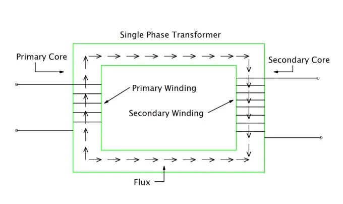
Single Phase Transformer Core:
The transformer’s main element exists within its core structure. The device consists of silicon steel sheets of thin lamination that are layered into stacks. To lower eddy current losses while increasing efficiency, insulation coats the lamination. Magnetic flux that originates from the primary winding finds its pathway inside the core structure. The transformer design minimizes its size Magnetic flux resistance since this configuration ensures optimal flux connection with both windings.
There are two fundamental design types of transformer :
- Core type: The core accepts windings positioned on its left and right (limb) sections.
- Shell type: Each winding operates on the central limb although the core wraps all around the windings.
Single Phase Transformer Windings.
The number of windings turns determines the transformation ratio to increase or reduce electrical voltage.
- Primary Winding: The input AC supply connects to this section. A magnetic field develops inside the core when primary winding current flows.
- Secondary Winding: Connected to the load. The transformer obtains an induced voltage that comes from the generated magnetic field.
The transformer case functions as its shielding component, which serves as both tank and enclosure structures. The voltage increases through the transformation process when secondary winding turns surpass those of the primary winding. The insulation of windings plays an essential role to prevent Electrical breakdowns as well as short circuits.
Insulation
The safety of operation depends on suitable insulation measures. The insulation component separates cable windings while shielding both windings from water entry and excessive heat generation. insulation materials include flowing elements:
- Varnish
- Pressboard
- Kraft paper
- Polyester films
The transformer operates reliably and securely due to proper insulation methods.
Transformer Tank or Casing
The distribution system operates to share electric load capacity between transformers. The transformer tank exists as metal material that defends internal components against dust particles as well as liquid exposure and mechanical interference. The tank contained within oil-filled transformers acts as an oil reservoir both for cooling operations and insulation functions. Plastic enclosures serve transformers in small dimensions, especially when used in residential devices.
Cooling System (If Needed)
Operation of the transformer leads to heat production. Natural air cooling functions as the sufficient cooling method for smaller transformers. Larger transformers depend on transformer oil as a heat absorption and heat transport fluid. Prolonged cooling of oil-filled transformers may occur through radiator and fan installations.
Bushings
Windings lead to external circuits through insulated bushings that serve as terminal connectors. These components enable proper wire attachment to the transformer. The insulation material of bushings is either porcelain or resin with the purpose of blocking current leakage.
Types of Single Phase Transformers
The power distribution system utilizes 1 phase transformers for voltage increase or decrease purposes in residential homes and business establishments as well as small industrial sites. The classification of single-phase transformers takes place according to their construction method along with application and usage pattern.
Based on Construction
- Single Phase Step Up Transformer: A step-up transformer is primarily designed to transform an input voltage to a higher voltage. The primary windings of this transformer supply the input voltage, while the secondary windings connect the load. Its secondary winding has a higher number of turns than the primary. It is primarily used in power grids, electrical appliances, industrial machinery, and domestic applications.
- Single Phase Step Down Transformer: A step-down transformer has a lower output voltage than its input voltage. Its secondary winding has fewer turns than its primary winding. This transformer reduces the input voltage to a safe and usable output voltage.
Based on Mounting
- Single-Phase Pole-Mounted Transformer: This transformer is used in power distribution systems. It is mounted on a pole, hence the name. It is primarily used to supply electricity to rural and suburban areas where high voltage needs to be converted to lower voltage. It is safely used in most homes, farms, and small businesses.
- Single-phase pad-mounted transformers: These transformers are mounted on concrete pads elevated above the ground and secured within locked cabinets. These transformers are used in underground power distribution networks and are protected from public access. They are primarily used in urban and suburban areas, where underground power distribution systems are preferred.
Based on Cooling Method
- Air-Cooled (Single phase dry type transformer): The cooling system of this transformer operates through air circulation. These units remain safe for indoor spaces while power systems of small capacities use them.
- Oil-Cooled Transformer: These transformers use mineral oil both for insulation plus cooling functions. Such transformers excel at larger power demands, and they find their primary use outdoors.
Operation of Single Phase Transformer
Single phase transformer working is given below step-by-step:
- Supply of AC Voltage: A primary winding receives AC voltage supply which creates an electrical current to flow.
- Generation of Magnetic Field: An alternating magnetic field appears inside the core because of flowing current.
- Induction in Secondary Coil: The induced magnetic field from the primary connects to the secondary winding thus producing an EMF inside the coil.
- Power Transfer: Power transmission occurs through the secondary circuit once it is closed to connect with the load.
The 1 phase transformer operates with an efficiency greater than 95%, thus demonstrating its reliability for power transfer purposes.
Single Phase Transformer Phasor Diagram.
A transformer displays its voltage and current relationship with flux through a graphical representation called phasor diagram. A phasor diagram reveals time-based quantifiable relationships between electromagnetic amounts while displaying these quantities through angular representations of size.
A 1 phase transformer reveals its phasor pattern through double aspects: load presence or absence along with resistive, inductive or capacitive load types. We will examine transformers under two conditions: first as an unloaded device and second when operating with an inductive load since this configuration is the most recurrent case.
No-Load Condition
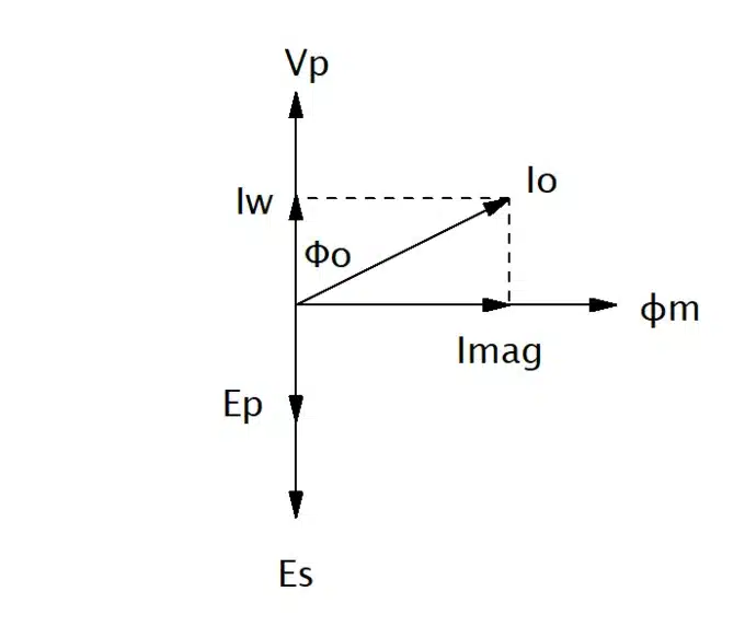
- The transformer experiences no-load conditions when it receives entrance from an AC supply but lacks secondary side connection.
- The reference phasor uses the primary voltage (V1) for its basis.
- A tiny currents (I0) passes through the primary winding under no-load conditions.
- Such current maintains a wide angle shift from the voltage because it creates mostly magnetic effects.
- The magnetic flux maintains the same phase relation with the magnetizing current.
- The EMFs (E1 and E2) developed in the primary and secondary windings face opposite directions as a result of Lenz’s Law.
On-Load Condition (Inductive Load)
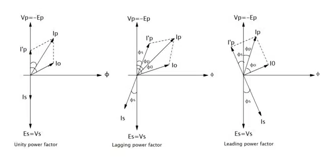
- The secondary circuit (I2) starts flowing because of inductance and it trails behind the secondary emf (E2).
- The main current (I1) builds up for equalizing the secondary force.
- The overall magnetic flux value (Φ) experiences minimal change.
- Small phasors located in the diagram display the voltage drops that occur within each winding.
Single Phase Transformer Price
Single-phase transformer prices depend on several essential factors, which include two main factors and three secondary factors.
- Voltage levels (input/output)
- Power rating (kVA or VA)
- The core material consists of either copper and aluminum windings.
- Brand and warranty
- Cooling type (air-cooled or oil-cooled).
The costs for custom-built or industrial-grade transformers depend on their safety features and how they fulfill basic requirements.
Application of the Single Phase Transformer
Various locations utilize 1 phase transformers as standard equipment. The primary utilization areas of these transformers will be explained in detail.
Commercial Buildings
- The supply of electricity runs through lighting systems along with small equipment within buildings.
Industries
- Control circuits along with small-scale machines in small industries operate using single-phase transformers.
Residential Use
- The step-down process reduces 230V to 110V power and its reverse operation is also feasible.
- Home appliances with televisions and refrigerators among them utilize transformers.
Rural Electrification
- The rural areas that do not receive three-phase power supply need transformer solutions.
Battery Chargers
- A transformer decreases voltage while it charges electrical batteries.
Renewable Energy Systems
- The conversion of voltage in solar and wind energy systems happens with the use of transformers.
HVAC Systems
- Heating ventilation and air conditioning systems implement these transformers for operational purposes.
My Personal Experience: We can assist you with selecting the suitable transformer. Our team will assist you to discover a suitable transformer when you need one for building projects or system improvement. We provide free consultation services to anyone who contacts us at this time.
Parallel Operation of Single Phase Transformer
Two transformers used in parallel configuration can distribute total electrical load between them. Power systems widely use this arrangement for enhancing flexibility while guaranteeing reliability and better controlling load requirements.
1 phase transformers join their efforts to serve a shared load when arranged in parallel operating configuration. The method proves essential to spread electricity load capacity between transformers. Because individual transformers cannot take all the current or to provide backup protection to the system.
What Are the Reasons Behind Using Parallel Operations?
- Load Sharing: Multiple transformers run the complete total of load current between them.
- Backup Supply: Transformer failures do not cause other units to stop operating.
- Future Expansion:The system enables simple addition of extra transformers at any time.
- Better Efficiency:The size of transformers allows for being turned on or off independently depending on current load requirements.
Conditions for Parallel Operation
Multiple conditions need to be maintained for correct operation of parallel systems.
- Same Voltage Ratio: All transformers within parallel operation must maintain an identical ratio between primary and secondary voltage.
- Same Polarity: The operation between transformer windings remains safe because of such implementation.
- Same Phase Sequence: For three-phase systems, but not applicable for single-phase.
- Same Frequency: Each transformer requires operation under identical frequency value.
- Equal Per Unit Impedance: Equality in load distribution will not occur when these requirements are not followed.
Peaceful transformer operation requires that these standards need to be met else it will cause circulating currents and decreased efficiency levels.
Conclusion
Electrical devices classed as 1 phase transformers operate as basic yet essential components that power our daily lives through changing electricity voltage levels securely and effectively. The device operates as a safe and efficient system to transform voltage across different electrical setups. Single phase transformers exist in every electrical system to deliver power for homes or appliances or rural-area electricity supply across the nation.
FAQ
What is a single-phase transformer?
The single-phase transformer acts as an electrical instrument that transfers power while using single-phase AC supply to operate electromagnetic inductance between circuits.
What is the working principle of a single-phase transformer?
The principle of Faraday’s Law sets the foundation for a changing magnetic field to produce a voltage across the secondary winding.
Where are single-phase transformers commonly used?
These devices enable homes and small offices and shops along with rural areas to obtain power for lighting purposes, air conditioning and heat generation and motor function.
What is voltage regulation in a single-phase transformer?
The voltage difference between secondary circuits from no-load operating to full-load operation under constant primary voltage defines the percentage.
Can a single-phase transformer work on DC supply?
The device fails to operate with DC electricity since its operation depends on a shifting magnetic field created by AC power.
How do you test a single-phase transformer?
The core losses get determined through an Open Circuit Test followed by a Short Circuit Test that reveals copper losses and impedance values.
I am an electrical engineer and also a blogger. I write informative blog posts on topics related to electrical and electronics engineering. If you are interested in these topics, you are welcome to my site to read these articles.