Construction and Working Principle of Transformer
Function of transformers as one of the basic electrical components which maintain essential roles during the movement and delivery of electric power from generation sites to end-users. A transformer operates as an electrical machine that conducts electrical power between multiple circuits through electromagnetic production. As fundamental electric devices transformers work to enable secure effective power transmission across extended distances while regulating voltage values to match various electrical devices and systems. This article explains the working principle of transformers, how different types work, their construction, and the transformation process that matters in the existing electrical infrastructure.
Parts of a Transformer
A transformer is a static device, meaning it has no moving parts. However, its internal architecture is complex. Understanding the various transformer components is crucial for grasping how this device efficiently transfers electrical energy between circuits.
While the specific design might vary depending on the application—from small electronics to massive power grids—the fundamental structure remains consistent.

The primary elements responsible for the device’s operation are the transformer core and winding. These work together to facilitate electromagnetic induction. Beyond these central elements, several other parts ensure insulation, cooling, and protection. Let us understand the important parts of an electrical transformer one by one:
Magnetic Core
The core acts as the backbone of the transformer. It provides a low-reluctance path for the magnetic flux to flow. To minimise transformer losses, such as eddy-current and hysteresis losses, the core is typically constructed from thin, laminated sheets of soft iron or silicon steel. This magnetic core is vital for coupling the two circuits magnetically.
Transformer Windings
Windings are coils of wire wound around the core. They carry the electrical current and are usually made of high-conductivity copper or aluminium to reduce resistance. There are two distinct types of windings:
- Primary Winding: This coil is connected to the electrical supply. It receives the input voltage and creates the initial magnetic flux.
- Secondary Winding: This coil is connected to the load. The changing flux from the core induces a voltage in this winding, which then delivers the transformed energy to the output circuit.
Insulation Material
Since the windings are carrying different voltage levels and are wrapped closely together, robust insulation is necessary to prevent short circuits. Insulation materials separate the windings from the core and from each other. Common materials include insulating oil, paper, varnish, and wood. Proper insulation ensures the device’s safety and longevity.
Tank or Main Body
The tank is a robust container, usually made of steel, that houses the core and windings. It protects these internal components from external factors such as rain, dust, and moisture. In oil-filled transformers, the tank also holds the cooling oil.
Transformer Oil
In many large transformers, the tank is filled with a specific type of mineral oil. This oil serves a dual purpose: it acts as a liquid dielectric (an insulator) between the conducting parts and the tank, and it helps dissipate the heat generated during operation.
Cooling System
Transformers generate heat due to copper and iron losses. If this heat isn’t managed, it can damage the insulation and lead to failure. The cooling system varies by size. Small transformers may rely on natural air cooling, while larger industrial units use radiators, fans, or oil-circulation pumps to maintain optimal operating temperature.
Terminals and Bushings
These are the connection points where the external input and output wires connect to the internal windings. Bushings act as insulators, allowing the high-voltage conductors to pass through the grounded tank safely without creating an electrical arc.
Breather
For oil-filled transformers, a breather is essential. As the oil heats up and cools down, it expands and contracts, pushing air in and out of the tank. The breather contains silica gel to filter moisture out of the air entering the tank, preventing contamination of the oil.
Working Principle of Transformer
The transformer working principle is based on the fundamental concept of mutual induction between two circuits linked by a common magnetic field. Essentially, a transformer transfers electrical energy from one alternating current (AC) circuit to another without changing the frequency, usually altering the voltage and current levels in the process.

To fully understand transformer operation, we must examine how electricity and magnetism interact within the device. The entire process relies on Faraday’s law of electromagnetic induction, which states that a changing magnetic field within a closed loop induces an electromotive force (EMF) in the wire.
Step-by-Step Transformer Operation
How a transformer functions, let me know:
- Input Supply: An alternating voltage source is connected to the primary coil (or primary winding). As AC flows through this coil, it constantly changes direction and magnitude.
- Creation of Magnetic Flux: Alternating current flowing through the primary coil produces an alternating magnetic flux surrounding the coil. Because the coils are wound around a high-permeability magnetic core, this flux is confined to the core rather than scattering into the air.
- Mutual Induction: This alternating flux flows through the core and links with the secondary coil (or secondary winding). Even though there is no direct electrical connection between the primary and secondary coils, they are magnetically coupled.
- Induced EMF: According to Faraday’s law of electromagnetic induction, the changing magnetic flux linking the secondary coil induces an EMF (voltage) across it. This is the core of the transformer working principle.
- Voltage Transformation: The magnitude of the induced voltage depends on the number of turns in the coils.
- If the secondary coil has more turns than the primary, the voltage increases (Step-up).
- If the secondary coil has fewer turns, the voltage decreases (Step-down).
- This process results in efficient voltage transformation suited for transmission or end-use.
- Load Connection: When a load (like a light bulb or machine) is connected across the secondary terminals, the induced voltage drives a current through the load, completing the transfer of power.
Key Factors in Transformer Operation
The efficiency and effectiveness of the transformer operation depend on several critical factors:
- Turn Ratio: The ratio of the number of turns in the primary coil to the secondary coil determines the voltage output.
- Turn Ratio: The ratio of the number of turns in the primary coil to the secondary coil determines the voltage output.
- Frequency Stability: The frequency of the input supply (e.g., 50Hz or 60Hz) remains the same on the output side; transformers only change voltage and current, not frequency.
Voltage Induction
The resulting voltage in the secondary coil amounts to the product of primary winding turns relative to secondary winding turns. The number of turns in secondary and primary coils determines whether the circuit experiences voltage stepping up (increased) or stepping down (decreased).
Power Conservation in Transformers
A primary coil input of alternating voltage creates an alternating magnetic field within the core material. The secondary coil produces voltage due to Faraday’s Law of Induction as the magnetic field changes.
The number of coil turns in both primary and secondary sections defines the voltage strength that appears in the secondary coil. An ideal transformer functions without power loss through constant preservation of electrical energy.
Real transformers suffer from several efficiency losses which originate from copper resistances in the windings and magnetic field behavior in the core material.
Efficiency of Transformers
When evaluating electrical machines, transformer efficiency stands out as remarkably high compared to that of rotating machinery. Since there are no moving parts, friction and windage losses are nonexistent. This structural advantage means that a well-designed transformer can achieve efficiency levels often exceeding 95% to 99%.
However, no device is perfectly efficient. While the transformer working principle relies on the seamless transfer of energy from the primary to the secondary circuits, some energy is inevitably lost in the process, usually as heat. Understanding these losses is key to optimising transformer operation and ensuring longevity.
Efficiency is defined as the ratio of power output to power input. In mathematical terms:
Since Power Input = Power Output + Losses, the efficiency can also be expressed as:
Types of Losses Affecting Efficiency
To maximise transformer performance, engineers must minimise the two primary types of energy losses that occur during operation:
Iron Losses (Core Losses):
These losses occur in the magnetic core and are constant, regardless of the load connected to the transformer. They depend on the material’s magnetic properties and the supply voltage.
- Hysteresis Loss: This occurs due to the repeated magnetisation and demagnetisation of the core material as the alternating current cycles.
- Eddy Current Loss: Circulating currents induced within the metal core itself generate heat. Laminated cores are used to reduce this specific loss.
Copper Losses (Ohmic Losses):
Unlike iron losses, copper losses vary significantly with load. As the load on the secondary winding increases, the current flowing through both windings increases. Since the windings have internal resistance (R), power is dissipated as heat according to the formula I2R. These are the most significant sources of energy waste during heavy load conditions.
Types of Transformers and their Working Principle
Step Up Transformer
A Step-Up Transformer is an electrical transformer designed to increase the voltage from the primary to the secondary. While it increases voltage, it simultaneously decreases current to maintain power balance, in accordance with the law of conservation of energy. This device is a critical component of modern power network infrastructure.

Its core function relies on the standard transformer working principle, with a specific coil configuration to achieve the desired voltage boost. By manipulating the ratio of turns between the input and output windings, engineers can precisely control the amount of voltage increase.
Working Principle of Step Up Transformer
The mechanics behind this device are straightforward when examining the transformer operation:
- Winding Configuration: In a step-up transformer, the secondary winding has a significantly greater number of turns than the primary winding.
- Voltage Increase: As the alternating current flows through the primary coil, it creates a magnetic flux. Because the secondary coil has more turns, cutting this flux, the induced electromotive force (EMF) exceeds the input voltage.
- Current Reduction: Since Power (P) equals Voltage (V) times Current (I) (P = V I), and power remains roughly constant (minus minor losses), an increase in voltage leads to a proportional decrease in current.
Step Down Transformer
A Step Down Transformer is the counterpart to the Step Up Transformer, serving a vital function in the final stages of the power delivery system. Its primary role is to decrease the input voltage to a safer, usable level for various applications. While high voltage is necessary for efficient transmission, it is far too dangerous and impractical for end-users; this is where the step-down transformer becomes essential.
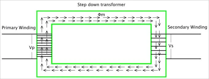
The device operates on the same core-transformer working principle as other types, but its internal architecture is reversed to achieve voltage reduction. By altering the magnetic coupling between coils, it converts high-voltage, low-current Power into low-voltage, high-current Power.
Working Principle of Step Down Transformer
To understand the transformer operation in a step-down configuration, we look at the arrangement of its windings:
- Winding Ratio: In a step-down transformer, the primary winding has a large number of turns, while the secondary winding has significantly fewer turns.
- Voltage Drop: When high voltage enters the primary coil, it generates a magnetic flux. Because the secondary coil has fewer turns interacting with this flux, the induced voltage is lower than the input.
- Current Increase: Following the principle of conservation of energy, as the voltage drops, the available current (amperage) increases on the output side, making it suitable for driving heavy loads.
Single Phase Transformer
Single phase transformer also works on Faraday’s principle of electromagnetic induction. It has two windings, primary and secondary, which are insulated and wrapped on an iron core. Single phase transformers are used to step down or step up the voltage in domestic and small industries.
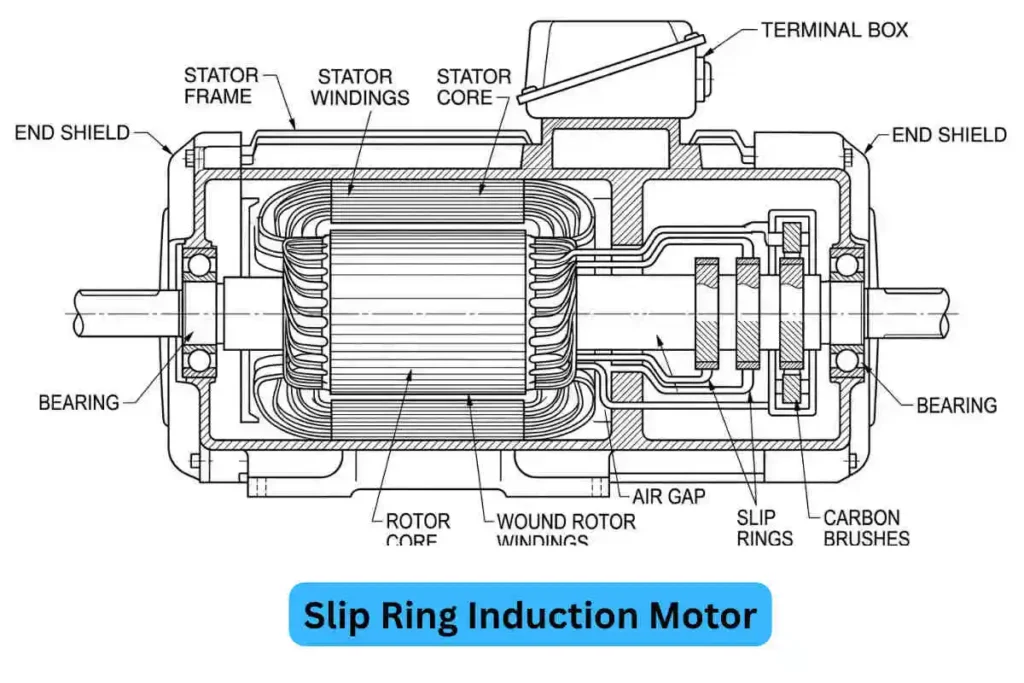
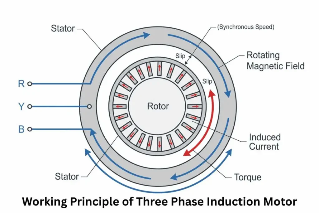
Three Phase Transformer
The three-phase transformer serves to transform three-phase electrical systems that prevail within industrial facilities along with major commercial operations. The voltage of three-phase power systems can be increased or decreased through three-phase transformers making them superior for electric power transmission.
Working Principle of 3 Phase Transformer
Each phase of the three-phase transformer system uses an individual separate winding. The windings function together in perfect synchronization to both increase and decrease voltage levels across every phase leading to balanced power delivery.
Isolation Transformer
A device needs an isolation transformer to maintain an isolated connection from its power source. The transformation function of this device does not adjust voltages but serves to separate the electrical paths between its primary side and secondary side.
An isolation transformer serves three essential functions: it protects equipment from electrical shock, reduces power-related noise interference and generates a steady power supply for delicate systems.
Isolation Transformer Working Principle
An isolation transformer functions by preserving the identical ratio between its primary and secondary winding voltages. The transformer does not modify the voltage level but it separates the secondary electrical pathway from the primary.
Autotransformer
An autotransformer functions by using one winding as both primary and secondary parts. An autotransformer adopts one winding mechanism instead of distinct windings to create an improved and reduced design.
Auto Transformer Working Principle
During operation an autotransformer delivers some input voltage directly to the load yet adjusts remaining voltage by using the common winding section. The efficient design enables lower losses thus making these transformers superior to conventional ones for some application scenarios.
Toroidal Transformer
A toroidal transformer takes a ring-shaped form instead of utilizing typical rectangular or square cores for transformation purposes. A continuous wind of ferromagnetic material makes the core which the winding encircles. Toroidal transformers possess both small size characteristics and operational efficiency features.
Toroidal Transformer Working Principle
The operation of toroidal transformers proceeds according to the traditional transformer working mechanism involving electromagnetic induction. The toroidal design provides both a high efficiency rate along with decreasing stray magnetic field strength that results in minimal power waste and interference.
Pulse Transformer
A pulse transformer functions as a device which delivers electric pulses rather than handling consistent signals. Such devices operate for fast switching of high voltages within radar systems alongside communication systems as well as applications that need pulse transmission.
Telecommunication systems depend on pulse transformers to properly transmit high-frequency signal signals efficiently. The design of pulse transformers facilitates digital signal conversion during control system operations along with signal processing duties.
Pulse Transformer Working Principle
A pulse transformer produces quick voltage variations through its pulse output mechanism. The design of the device specializes in transmitting rapid brief high-frequency signals which set it apart from other transformers that process consistent currents.
Instrument Transformer
The proper calculation of electricity usage depends on instrument transformers which provide current and voltage measurements for electric circuits during billing procedures. The devices operate within power grid protection systems to monitor circuit faults by measuring both current and voltage levels.
Instrument Transformer Working Principle
The Current Transformers (CTs) lower high current levels to measurement-ready values that are usable by meters and relays to prevent harmful exposure to sensitive equipment. Voltage Transformers (VTs) provide power utilities with the functionality needed to transform high voltage levels down to lower levels suitable for control system monitoring operations.
Conclusion
From the high-voltage transmission lines that crisscross our landscapes to the small adapters that power our daily gadgets, transformers are indispensable cornerstones of modern electrical systems. By understanding their construction—from the laminated core and copper windings to the essential cooling and insulation systems—we gain insight into their remarkable efficiency and reliability. The fundamental working principle of transformer technology, based on electromagnetic induction, enables seamless conversion of voltage levels.
FAQ
What is the basic construction of a transformer?
The construction for effective transformer operation primarily consists of a magnetic core made of laminated steel and two sets of windings (coils) made of copper or aluminum. It also includes insulation materials, a tank for protection, and often a cooling system like oil or fans.
Can a transformer work with DC supply?
No, a transformer cannot work with direct current (DC) because proper transformer operation depends on an alternating current (AC) to create the changing magnetic flux necessary for induction. Connecting a transformer to a DC supply can damage the windings due to excessive heat.
What is the working principle of a transformer?
In transformer operation, the device works on the principle of mutual induction.
What is the role of transformer oil?
Transformer oil serves two main purposes during transformer operation: it acts as an electrical insulator to prevent short circuits between internal parts, and it acts as a coolant to dissipate the heat generated during operation.
I am an electrical engineer and also a blogger. I write informative blog posts on topics related to electrical and electronics engineering. If you are interested in these topics, you are welcome to my site to read these articles.