What is the Transmission Line: Principle, Role & Types
The electrical power system functions through the fundamental component of transmission lines. Utility facilities utilise an electric line to move electrical energy from power generation sites to substations, which further distribute the power to residential consumers throughout extensive networks. Electricity delivery depends entirely on high-tension lines for both effectiveness and reliability.
This article examines the entire scope of transmission lines through their definition as well as types of components, working advantages, disadvantages, and future prospects.
What is the Transmission Line?
The transmission line is that part of the power system that transfers electrical energy from one place to another place, like delivering electricity from power plants to consumers. It works on a high voltage and covers a longer distance.
Power lines represent specially constructed electrical power and signal distribution structures designed for long-range intercity and city connection applications. The system moves electricity from power generation sites through substations until it reaches the distribution systems that serve residential as well as commercial and industrial establishments.
EHV lines support signalling processes through telecommunication networks as well as radio and TV broadcasting operations. The transmission system consists mainly of supportive structures that include conductors and towers or poles where wires bear the electrical load. When transmitting signals, the same transmission power lines serve as the basis for delivering the information signals through
Key Features :
- Transports high-potency electricity.
- Brings power stations to sub-stations.
- It reduces line losses and voltage drops.
- It is made from materials such as aluminium or copper.
Purpose :
- Effective transmission of energy to the cities or regions.
- Transformers are used in the process of step-up and step-down.
- Maintain the reliability and stability of systems.
Transmission Line Theory
The transmission line theory is founded on the behaviour of the electric current and voltage along a conductor in a considerable length. Electric lines have some special characteristics that are different from simple electrical circuits because they are long and operate at a frequency.
Important Concepts:
- Distributed parameters: The resistance, inductance, capacitance, and conductance are not lumped but are distributed along the length.
- Wave propagation: The behaviour of voltage and current at high frequency or long-distance transmission resembles a wave.
- Characteristic impedance: Each transmission power line has an impedance that depends on its shape and construction material.
The behaviour of the High Tension line:
- Its current and capacity vary along the line.
- Reflections can be attained when the line does not have an appropriate end.
- Power requires matching; it has to be matched.
Types of Transmission Lines and Their Uses
Types of Transmission Lines
Long transmission lines serve as an electric power system that transmits energy from power generation centres to end-use centres located at a distance. High tension lines are classified according to several factors, including voltage levels and distance along with construction aspects.
Based on Distance and Voltage
- Short transmission line: The length of such a line is 80km, and the voltage is less than 20kv. Such lines receive use in short-distance power transmission networks such as local distribution systems as well as small-area transmission systems.
- Medium transmission line: The length of this type of line ranges from 80 km to 250 km, and the voltage ranges from 20 kV to 100 kV. The application of such lines supports power transmission across medium distances for both regional and sub-regional transmission networks.
- Long transmission line: The length of such a line is more than 250 km, and the voltage is more than 100 kV. The purpose of using such overhead line extends to high-voltage power transmissions across extended distances between power plants and urban centers.
Based on Construction Type
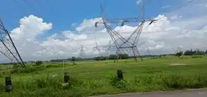
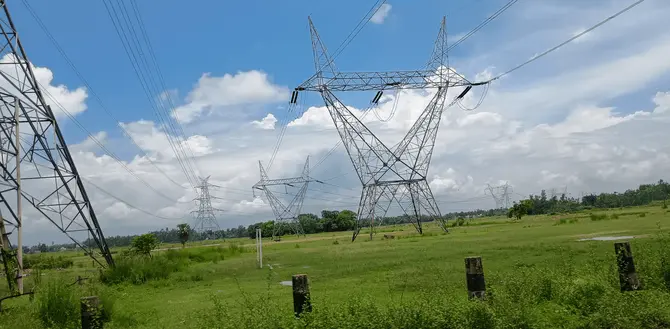
1. Overhead Transmission Line
Towers above the ground surface that uses suspended conductors are the primary type of overhead power line. This type of line is called an overhead line. Insulators are used on these towers to prevent electrical leakage while maintaining the transmission conductors, and aluminium or aluminium alloy structures are used on the supporting poles.
Advantage: Electricity overhead lines offer three significant advantages, having affordable costs while providing convenient servicing capabilities and serving as suitable power carriers over extended distances.
2. Underground Transmission Line
When overhead lines become unusable for practical purposes for some reason, underground transmission lines are used underground in urban locations. Irrigation pipelines contain buried cables that receive insulation through the application of rubber and oil layers to protect them.
Advantages: These lines provide an excellent appearance and function better in various weather conditions while creating safety advantages for urban locations.
3. Submarine transmission line
Underwater power transmission exists as a specific line type that delivers electricity across water bodies when connecting islands or passing through waterways.
Electricity transmission through submarine areas depends on installing insulated cables which remain underwater on the seabed and under seabed surfaces.
Advantages: The transmission of power across bodies of water requires these lines as the only option when direct land-based transmission is not feasible.
Based on Current Type
1. AC Line
Power systems heavily utilise the AC transmission system as it exists as the primary transmission method. These electric lines operate with a current that changes direction at specified frequencies of 50 Hz or 60 Hz, depending on the geographic area.
Transmission lines based on alternate current technology possess three conductive elements for three-phase applications along with single conductors for single-phase applications coupled with insulators and tower supports.
Advantage: AC power benefits from three main advantages, which include transformer-based voltage transformations, cost efficiency for long transmission distances, and capable performance of large-scale distribution.
2. DC Line
The operation of DC line involves the single-directional flow of electric current. DC provides constant current as it does not oscillate, which results in it being used in specific applications where a steady flow is required.
When constructing DC power lines, operators install them either above or below ground and employ advanced conversion technology at both ends (DC to AC at the transmitter and AC to DC at the receiver).
Advantage: Lower line losses over very long distances, better for underwater and underground transmission, no reactive power loss, more stable for specific applications like HVDC (High Voltage Direct Current) systems.
Basic principle of transmission line
The primary purpose of transmission lines is to transmit electrical power starting from generating stations through substations until it reaches final consumers. High power tension lines operate through essential components that allow electricity transmission across extended distances by reducing losses in power delivery.
Initially, at power generation stations, the electricity is maintained at a low voltage between 11 kV and 33 kV. The need for efficient long-distance transmission drives a step-up process through step-up transformers.
Different transmission systems utilise voltage levels of 132 kV, 220 kV, and 400 kV. High-voltage transmission systems reduce current flow and achieve weightless energy consumption due to I²R power losses.
Power Transmission
After voltage elevation, the electricity moves through aluminium or ACSR conductors, which operate on transmission towers. Such conductors are specifically engineered to maintain low energy losses together with the ability to endure wind conditions and temperature variations.
The power generated at the generating station moves toward substation areas through an overhead power line.
Voltage Step-Up
The transmission of high-voltage electric power stops at substations where it obtains step-down transformation for safety levels between 11 kV and 33 kV. The decreased voltage level is appropriate for distributing power to homes and businesses, together with industrial facilities.
Energy Losses
Transmission power lines maintain excellent efficiency but have some losses due to the resistive, inductive, and capacitive properties present in the conductors. High-voltage transmission serves as a loss-minimising solution because it minimises the electric current flowing in the conductors.
The transmission line function works through voltage elevation for extended transmissions, followed by loss reduction before lowering voltage levels for consumer safety delivery.
The Role of Transmission Lines in Electrical Power Systems
We can get an idea of how important electricity is for us if it is not available 24 hours a day. Similarly, transmission lines are the primary source of supplying electricity to us. Let us know in detail:
1. Transportation of electrical energy
- Power lines transmit electricity efficiently over long distances.
- Electricity is transmitted at high voltage to reduce energy losses.
2. Reducing energy loss
- Transmitting electricity at a higher voltage reduces the current, which reduces energy losses in the line, such as heat loss.
- Transformers are used to increase or decrease the voltage.
3. System Reliability
- High power tension lines increase the reliability of an uninterrupted supply of electricity.
- These connect all the production centres and consumers, thereby maintaining a balance between demand and supply of electricity.
4. Helpful in Economy and Development
- EHV lines ensure the uninterrupted availability of power, which is essential for economic growth and social progress.
Transmission Line Components
Multiple essential components in power lines establish a unified system that transfers electrical power efficiently over safe distances.
- Overhead Conductors: The electric current passes through this overhead conductor. The preferred materials used in the construction of HV lines are aluminium and steel. Copper is used sparingly.
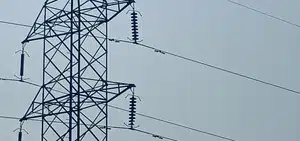
- Transmission Line Towers: Overhead line structures serve to maintain the conductors used at a safe height and distance from other objects and ground surfaces.
- Insulators: Transmission line insulators act as a support as well as an insulation that protects the conductors from touching transmission towers or poles, as well as preventing leakage of electric current.
- Grounding wire: A grounding wire enables controlled electrical current flow to the earth for fault protection, which safeguards transmission equipment and systems.
- Transformers: The voltage level is adjusted through transformers for transmission and distribution purposes.
- Circuit Breakers and Switches: High voltage electricity lines receive their control functions and protective elements through specific devices. Power lines are protected from dangerous high currents by circuit breakers, while electrical isolator switches ensure that the lines remain isolated during maintenance procedures.
- Corona Rings: Corona rings decrease the frequency of corona discharges occurring at conductor and insulator ends before they cause power loss alongside equipment destruction.
- Lightning Arresters: The system should have lightning arresters to protect it from damaging voltage surges when lightning strikes.
- Splice Joints: Electric line expansion and contraction because of temperature changes leads to the use of splicing connections between line segments.
- Continuous Earth Wire: To protect against lightning discharges, a continuous earth wire in the towers runs on top.
- Vee Guards: Vee guards are used to make power lines safe when they run over public roads so that they can be protected in case of a break.
- Barbed Wire: Barbed wire is wrapped up to a height of 2.5 meters above the ground of the tower so that no unauthorised person can climb it.
- Bird Guird: An evonite stick is fixed near the insulator to prevent flashover when a bird flies over it.
Transmission Line Parameters.
Transmission line parameters are the electrical properties that determine the behaviour of a high tension line when electrical power is transferred across it. These parameters are not supposed to be concentrated at a point but rather to be spread along the whole length of the line.
These affect the regulation of voltage, power loss, and propagation of waves, as well as the stability of the entire system. Four main parameters of the overhead power line include Resistance (R), Inductance (L), Capacitance (C), and Conductance (G). These are typically expressed as units per length (e.g., per kilometre).
Resistance (R):
- It is the resistance of the current flow through the conductor.
- R leads to power loss in the form of heat (I2R loss).
- It depends on the length of the line and the temperature.
- The unit is ohms per kilometre (Ω/per km).
Inductance (L):
- The phenomenon occurs as a result of the magnetic field around the conductor in which current flows.
- Due to the causes of reactive voltage drop and phase angle.
- It is dependent on the spacing and geometry of a conductor.
- Per kilometre (H/per km) is its measuring unit.
Conductance (G):
- Characteristic conduction current across the insulation.
- As a rule, it is extremely low in lines in a well-maintained condition.
- It will be important in wet or dirty conditions.
- It is measured In Siemens /km (S/per km).
Capacitance (C):
- It exists between conductors as well as between conductors and ground.
- It affects the current and voltage charging profile.
- It is more serious in underground cables than in overhead lines.
- Its measuring unit is Farad per kilometre (F/per km).
These parameters are critical in the analysis and design of overhead lines, where it is essential not to overlook their effects in the medium and long lines.
Transmission Line Diagram
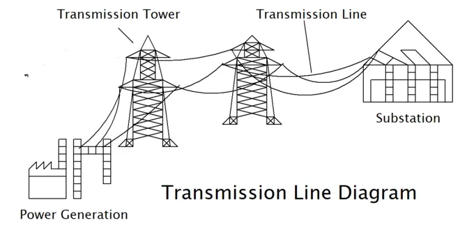
A transmission system diagram is a diagram charting the main components of an electric transmission system and the flow of electrical power between generating stations to a consumer via a substation and overhead electrical lines. These diagrams assist engineers, students, and utility professionals in obtaining visual relationships of electric power flows, the structure, and the voltages involved.
Simple items in a Transmission line Diagram:
- Generating Station: The voltage point where the electrical energy is generated is usually between 11 and 25 kV.
- Step-Up Transformer: Raises the voltage (e.g., 11 kV to 132 kV or more) to allow the electricity to be transmitted efficiently over a long distance.
- High Voltage Overhead Line: Transports power over long distances at high voltages (e.g., 132 kV, 220 kV, 400 kV or greater).
- Substation: The substation converts high-voltage power into low-voltage power so that it can reach the consumer safely and efficiently.
- Switchgear: Switchgear is used to open (disconnect) or close (connect) the power line.
- Circuit breakers: A circuit breaker is an automatic switch that disconnects an electrical circuit during fault conditions, such as short circuits or overloads.
- Reactors or Capacitors: Reactors are used to control reactive power and voltage regulation in electric lines. In transmission systems, capacitors are used to correct power factor, improve system efficiency, and reduce energy losses.
- Step-Down Transformer: Lowers voltage (e.g., a voltage of 132 kV to 33 kV or 11 kV) to be distributed to industrial, commercial, or residential consumers.
- Distribution Lines: A way that brings electricity to its final users at usable voltages, e.g., 440 V or 230 V.
Purpose of the diagram
- Voltages on various stages are displayed.
- Assists in fault analysis and system planning helps in system planning and fault analysis.
- Applied in design, protection, and control systems.
Transmission Diagram Type:
- Single Line Diagram (SLD) – Simplified.
- Phasor Diagram- Voltage and current relationships are indicated.
- Equivalent Circuits Model- Model applied to computation and prediction.
Transmission Line Voltage
Transmission line voltage is the voltage used by which electrical power originating at the generating station is then sent, on an electric line, to the distribution network. The level of voltage is a vital determination of the effectiveness, expense, and execution of a power transmission system.
Why is High Voltage Used?
High voltage power lines transmit power at a lower current in the conductor for the same amount of power, so I2R losses (power losses due to resistance) are reduced. Therefore, it enables long-distance power transfer with little loss of energy.
Common Voltage Levels in Transmission.
Depending on the distance and the power that has to be transmitted, there are several standard voltage levels at which transmission systems are operated:
Low Voltage (LV):
- The voltages below 1 kV
- Domestic and small-scale distribution intended usage
Medium Voltage (MV):
- 33kV to 1 kV
- It is appropriate for short transmission and primary distribution.
High Voltage (HV):
- 220 kV to 33 KV
- Employed for medium distances to transmit over long distances.
Extra High Voltage (EHV):
- 220 kV- 765 kV
- Applied in long-haul, high-load transmission schemes.
Ultra High Voltage (UHV):
- More than 800 kV
- Incorporated into the modern grid to send bulk power over very long distances.
Factors Influencing Voltage Selection
- Distance of transmission
- Amount of power to be transmitted
- Type of transmission system (AC or DC)
- Economic feasibility and insulation requirements
- Environmental and safety regulations
Losses in Transmission Line
The losses that result in power losses in transmission lines are the loss of electrical energy as heat or other forms of energy in the process of transferring power generated into distribution. The losses decrease the efficiency of the system as a whole and should be reduced to be able to operate it reliably.
Types of Power Losses:
1. Resistive Loss (I²R Loss):
- Caused by the resistance of conductors.
- The main form of loss in overhead lines.
- Increases with current and conductor length.
2. Corona Loss:
- Corona losses in transmission lines occur at high voltages due to the ionisation of air around the conductor.
- Produces a hissing noise and light, and leads to power dissipation.
Some losses may not be directly classified as losses, but they affect the performance and efficiency of the transmission line. Let us know about it.
Ferranti Effect
The Ferranti effect is seen in long power lines due to line capacitance. Due to this effect, the consumer end voltage becomes very high at the time of a light load.
Proximity Effect
The Proximity Effect occurs when the wires of a high-tension line are close to each other. Therefore, it causes uneven distribution of current, which affects energy loss and efficiency.
Skin Effect
In the skin effect, high-frequency current flows more on the surface of the conductor than inside. Therefore, it increases the effective resistance of the conductor, causing energy loss.
FAQ:
Why are transmission lines important?
The efficiency of electricity distribution depends on transmission lines because they enable power transfer over large distances. The ability to transport electricity long distances is only possible through transmission lines, since the generation of electricity stays local without them.
What are insulators in transmission lines?
The insulators serve two functions: they support conductors and defend against electrical current leakage to transmission towers. The manufacturing materials for insulators include porcelain alongside glass and composite polymers, which are non-conductive substances.
What is the purpose of a transmission tower?
The elevated position of conductors on transmission towers acts as a protective barrier that ensures their distance from trees, animals, and people. The structure offers physical resistance that enables it to endure various meteorological elements.
Why is the high voltage used in transmission lines?
The transmission process benefits from high-voltage power to decrease the amount of current through conductors and decrease resistive losses (I²R losses). The transmission system becomes more efficient for extended paths because of this method.
What are the main challenges of transmission lines?
Major obstacles affecting transmission lines include energy waste from transmission, difficulties in purchasing land and dealing with maintenance tasks in severe weather conditions, and problems stemming from the installation of enormous towers. The implementation of smart grids and HVDC systems has begun to resolve some existing issues.
How do transmission lines affect the environment?
Transmission lines result in visual disturbances that affect the environment and harm wildlife populations. The presence of overhead lines impacts the bird migration routes, while the land clearance for towers results in damage to natural ecosystems. Some environmental damage can be minimised through underground and underwater transmission systems.
I am an electrical engineer and also a blogger. I write informative blog posts on topics related to electrical and electronics engineering. If you are interested in these topics, you are welcome to my site to read these articles.