Electric Resistance - Simple Defination and How to Use
Table of Contents
ToggleElectric Resistance
In an electric circuit play an important role, this parameter is called electric resistance. This parameter alaways oppose the electric current in the circuit. Each metal has a tendency to oppose the current.
The S.I unit of resistance is ohm.there is collision between ions and free flowing electrons. This not only reduces the speed of electrons but also produces the heat. Due to this effect reduction of flow of current.
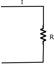
The resistance is denoted by the symbol R and is measured in ohm. Symbolically represented as Ω. The resistance of a circuit, in which a current of 1 ampere generates the heat at the rate of one joules per second is said to be 1 ohm.
Ohm's law
George ohm‘s state this law, this law which gives the relation between current, voltage and resistance in a closed electric circuit.
Ohm’s law state that in a closed circuit the strength of the current flowing through a solid conductor at constant temperature is directly proportional to the voltage across the conductor and inversely proportional to its resistance.
From definition
I∝V……..(i)
I∝1/R……..(ii)
Where V = electrical potential difference in V
R = electric resistance of the conductor in ohm (Ω)
from equation (i) and (ii) we get
I\propto \dfrac{V}{R}
I=K\times \dfrac{V}{R}
Where K is a constant
then from ohm’s law we get
I\propto \dfrac{V}{R}\times A
We can express this theorem in other words, this law states that the potential difference between the two ends of a conductor is directly proportional to the current flowing through it, provided its temperature and other physical parameters remain unchanged.
then V\propto I
or V=RI
Where R is constant of proportionally is called the electric resistance of the conductor. Its unit is ohm(Ω)
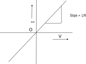
Ohm's Law in Graphical Form
The slope of the line is reciprocal of resistance (\dfrac{1}{r}) and is called conductance. The conductor in figure showing straight line ∨-i characteristics is said to have linear resistance.
Law's of Resistance or Factor Affecting the Resistance-
- length of the material :-- the electric resistance of a material is inversely proportional to the length.the length is denoted by l
- Cross - sectinal area :-- the electric resistance of a material is inversely proportional to the cross- sectional area of the material.more cross - sectional area allowed the passage of more.number of free electrons,the cross -section area is denoted by a
- Nature of material :-- the electric resistance of a conductor depends upon the material
- Temperature : --the electric resistance of a conductor depends upon the temperature.in a pure metal conductor,when the temperature increases the resistance also increases
From the above
r\propto \dfrac{l}{a}
r=\rho \dfrac{l}{a}
Where ρ is constant and is called the resistivity or specific resistance of the conductor,
l = length in meter
ρ = resistivity in ohm-meter
R = resistance in ohm’s
Limitation of Ohm's Law
Too many circuit elements do not follow ohm’s law its fails under the certain conditions
Resistivity
- V-I characteristic is not linear
- The relationship between v and i is not unique
- Nonlineer current is conduction through gases
- Devices where current decreases with increase in voltage the device is said to have negative resistance
The resistivity or specific resistance of a material depends on nature of meterial and denotedby ρ and is called rho.
It can be express as
\rho=\dfrac{ra}{l}
= \dfrac{\Omega m^{2}}{m}
= \Omega-m
Effect of Temperature on Resistance of Metal, Insulator, Alloys Electrolyte
- Resistor :-- a fixed resistance connected permanently in the circuit for limiting the current to a definite value is called resistor.
- Rheostat :-- a variable resistance by sliding contact on it is called a rheostat.the current flowing through the circuit is controlled by varying the resistance with the help of sliding contanct
- Potential divider :-- when a resistance is used to devlop a voltage drop,it is called a potential divider.
Effect of Temperature on Metal
Electric resistance of all the pure metals like copper, alluminium, iron etc. Increases linearly with temperature .In conductor increase in temperature, vibrations of irons increase but it does nor increase number of free electrons
Effect of Temperature on Carbon and Insulators
Electric resistance of carbon and insulators decreases as the temperature increases. Insulators do not have enough number of free electrons and therefore they are bad conductor of electricity.
In carbon and insulator due to increase in temperature, no doubt vibration of ions increases but due to high temperature few electrons from atom gain extra energy and made available as free electrons.
Therefore as number of free electrons increase though vibrations of ions increases overall difficulty to the flow of electrons reduces. This reason decrease in resistance.
Effect of Temperature on Electrolyte
Value of resistance of electrolytes decreases as the temperature increases. at high temperature they become extremely bad insulators.
Effect of Temperature on Alloys
The electric resistance of alloys increases as the temperature increases but rate of increase is not significant most alloys increase very slightly in resistance with a rise in temperature. Some alloys posses practically constant resistance at all temperature. This is very valuable making standard resistance.
Temperature Coefficient of Resistance
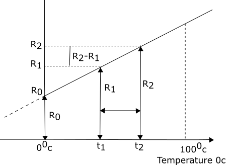
Suppose a conductor, the resistance of which increases with temperature linearly
let initial resistance at 0 0_{C}= R_0
resistance at t_{1}0_{C}=r_{1}
resistance at t_{2}0_{C}=r_{2}
in figure shown R_{2} >R_{1} >R_{0}
temperature coefficient of resistance at t0_{C} is the ratio of change in resistance per degree celcius to the resistance at t0_{C}
temperature coefficient of resistance at t0_{C} = \dfrac{\Delta R per 0_{C}}{R_{t}}= \alpha _{t}
from fig change in resistance = R_{2}-R_{1}
change in temperature = t_{2}-t_{1}
∴ change in resistance per 0_{C} = \dfrac{\Delta R}{\Delta t}
= \dfrac{R_{2}-R_{1}}{t_{2}-t_{1}}
then \alpha _{1} = \dfrac{change in resistance per 0_{C}}{resistance at t_{1}0_{C}}
= \dfrac{\dfrac{R_{2}-R_{1}}{t_{2}-t_{1}}}{R_{1}}
similarly temperature coefficient of resistance at
00_{C}
α_{0} = \dfrac{\dfrac{R_{1}-R_{0}}{t_{1}-0}}{R_{0}}
but \dfrac{R_{2}-R_{0}}{t_{2}-t_{1}} =\dfrac{R_{1}-R_{0}}{t_{1}-0} = slop of the graph
hence temperature of coefficient at any temperature t0_{C} can be expressed as
α_{t} = \dfrac{slope of the graph}{R_{t}}
the unit of temperature coefficient of resistance is per degree celcius /0_{C}
Calculating Resistance at t 0_{C}
temperature coefficient of resistance at 0_{C} = α_{0}
resistance at 0_{C} = R_{0}
resistance at t_{1}0_{c} = R_{1}
then α_{0} = \dfrac{\dfrac{R_{1}-R_{0}}{t_{1}-0}}{R_{0}}
= \dfrac{R_{1}R_{0}}{t_{1}R_{0}}
∴ R_{1}-R_{0} = α_{0}t_{1}R_{0}
R_{1} = R_{0}+α_{0}t_{1}R_{0}
= R_{0}\left( 1+\alpha _{t_{1}}\right)
thus resistance at any temperature can be express as
R_{t} = R_{0}\left(1+\alpha_{0}t\right)
Effect on Temperature on Resistivity
Let resistivity at t_{1}0_{C} = \rho _{1}
resistivity at t_{2}0_{C} = \rho _{2}
then temperature coefficient of resistivity at t_{1}0_{C} an be defined as
\alpha t_{1} = \dfrac{(\rho_{2}-\rho_{1})(t_{2}-t_{1})}{\rho_{1}}
similarly resistivity at time t0_{C} as
\rho_{t} = ρ_{0}\left(1+\alpha_{0}t\right)
\rho_{t_{2}} = \rho_{t_{1}}\left[1+\alpha_{t_{1}}\left(t_{2}-t_{1}\right)\right]
Resistance Connected in Three Types
1. Resistance Connected in Series
When electric resistance are connected end to end in such a very that there is only one path for the current to flow, then resistances are said to be connected in series and such circuit are known as series circuits.
If resistors R_{1}, R_{2} and R_{3} are connected a series,as shown figure.
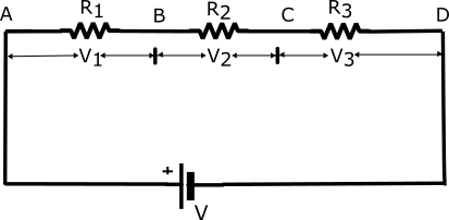
The total or equivalent resistance R = R_{1}+R_{2} +R_{3}………….+R_{n}.
We see that in series circuit there is only one path for the current to flow, but in an open circuit no current will flow through the circuit. that is why series circuit are not used in domestic connections.
these connections are used for
- Where a variable voltage is to be given to the load,like a fan regulator is connected in series with the fan.
- Many lamps which are of low voltage rating are operated by connecting in series with each other.
- Where a load of low voltage is to be operated on a higher supply voltage, a fixed value of resistance is connected in series with the load.
2. Resistance Connected in Parallel
When number of resistor are connected in such a way that all the entry ends are joined together at one junction and all the exit ends are connected together at another junction and there two junction are taken as terminals for supply, then such connection are known as parallel connection resistance.
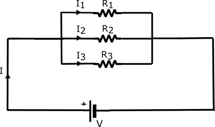
If resistors R_{1},R_{2} and R_{3} are connected in parallel as in figure.the total resistance R is given as
\dfrac{1}{R}=\dfrac{1}{R_{1}}+\dfrac{1}{R_{2}}+\dfrac{1}{R_{3}}
In general if n resistors of resistances R_{1},R_{2},R_{3}……R_{n} are connected in parallel, then total or equivalent resistance R of the circuit is given by
\dfrac{1}{R}=\dfrac{1}{R_{1}}+\dfrac{1}{R_{2}}+\dfrac{1}{R_{3}} +………..+ \dfrac{1}{R_{n}}
Parallel connection are used in all types of house and power wiring because in this connection the working voltage of the load is equal to the supply voltage.
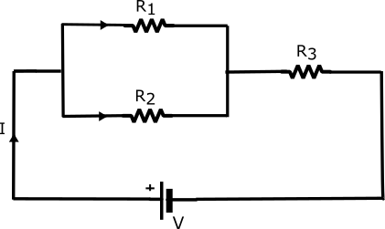
3. Resistance Connected in Series Parallel.
In this circuit thecurrent divides itself into two branches, as shown in figure
I am an engineer in a government department and also a blogger. I write posts on topics related to electrical and electronics engineering.
