Power Distribution System: What is and the Different Types
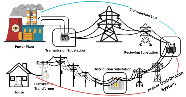
Electricity powers our homes, businesses, and hospitals, making modern life possible. Yet, we rarely think about the complex network that delivers it to us. The journey of electricity starts far away at power plants where energy is generated. From there, massive high-voltage transmission lines carry it across the country. Finally, the local power distribution system takes over. This system steps down the dangerous high voltage and delivers safe, usable power directly to your wall outlets.
This article breaks down exactly how that crucial final stage works. We will explore the types, components, and daily processes that make up power distribution systems. By the end, you will have a clear, comprehensive understanding of the silent infrastructure that keeps your lights on and your life running smoothly.
Power System Journey
The electricity powering your life travels an incredible journey before it reaches your home. To understand how power distribution systems work, we first need to look at the entire path electricity takes. This journey comprises three main stages: generation, transmission, and distribution.
Generation: Where the Power Begins
The journey of electricity begins at a power plant. In a power plant, raw energy derived from natural resources is converted into electricity. We use several methods to generate this energy, depending on available resources and technology.
- Thermal Generation: This method burns fuels such as coal, natural gas, or biomass to heat water and generate steam. The high-pressure steam spins a massive turbine, which is connected to a generator. Nuclear power plants work the same way, but they use nuclear fission to generate heat rather than burning fossil fuels. If you’re curious about how steam power plants work, you can explore our detailed article Steam Power Plant Working Principle?
- Hydroelectric Generation: Hydro plants use the natural flow of water to generate power. By building dams on large rivers, we control water releases. The force of the flowing water directly spins the turbines, creating clean, renewable energy.
- Solar Generation: Unlike thermal and hydro plants, solar power does not rely on spinning turbines. Photovoltaic (PV) panels absorb sunlight and convert it directly into electrical current using semiconductor materials.
At the core of most generators is a simple mathematical relationship. The electrical power (P) produced is the product of voltage (V) and current (I). We express this using the formula:
This generated power usually sits at a relatively low voltage, typically between 11 kilovolts (kV) and 25 kV. While this is enough to power a small local area, it is not efficient enough to travel hundreds of miles to distant cities.
Transmission: The High-Speed Electrical Highway
Once we generate the electricity, we must move it efficiently to where people need it. This brings us to the transmission stage. If we try to send electricity over long distances at the low voltage created at the power plant, we lose a massive amount of energy as heat along the wires.
To solve this problem, we rely on a fundamental principle of physics. The power lost as heat in a wire (Ploss) depends on the electrical current (I) and the resistance of the wire (R). The formula for this is:
Because the power loss increases with the square of the current, keeping the current as low as possible is crucial. To maintain the total power ($P = V \times I$) while reducing the current, we have to increase the voltage significantly.
This is the exact role of a step-up substation. Located right next to the power plant, these substations use large transformers to step up the voltage to incredibly high levels—often between 132 kV and 765 kV.
Once the voltage is stepped up, the electricity travels across the country on high-voltage transmission lines. These are the massive steel towers you see stretching across rural landscapes and highways. They transmit large quantities of electricity over very long distances, and energy wastage is also minimal.
Distribution: Delivering Power to Your Door
High-voltage electricity traveling on transmission lines is highly efficient over long distances, but it is far too dangerous to bring into a neighborhood or plug into a television. This is where the power distribution system takes over.
The transition from transmission to distribution happens at a local distribution substation. When the high-voltage electricity reaches the edge of a city or town, it enters this substation. Here, step-down transformers do the exact opposite of the power plant’s transformers. They lower the extreme voltages down to a much safer medium voltage, usually between 0.4 kV and 33 kV.
Once the voltage drops to a manageable level, the distribution system takes over completely. The electricity is transferred to primary distribution lines. These are the tubular poles, rail poles, or concrete utility poles you see lining neighborhood streets, or the thick cables buried safely underground in modern urban areas.
Finally, just before the electricity enters your home, it passes through one last transformer. You can identify them as metal cylinders mounted on utility poles or metal boxes placed on the ground. This final distribution transformer drops the voltage one last time to the standard 120 or 240 volts. The power then flows through a service drop wire directly into your home’s electrical meter, ready to power your life the second you flip a switch.
Types of Power Distribution Systems
Engineers design the networks that deliver electricity to your home or business to meet specific geographical, economic, and reliability-related requirements. These systems are classified based on their physical layout and the voltage levels they carry. Let us understand in detail the types of power distribution that constitute modern electrical grids.
Radial Distribution System
The radial distribution system represents the simplest and most traditional way to deliver electricity. Think of it like a tree. The substation acts as the trunk, and the power lines branch out to reach individual customers. Power flows in only one direction: from the source to the user.
Because of its straightforward design, a radial system is cheap to build and easy to maintain. You will commonly find this setup in rural areas or small towns where homes are spread out over large distances.
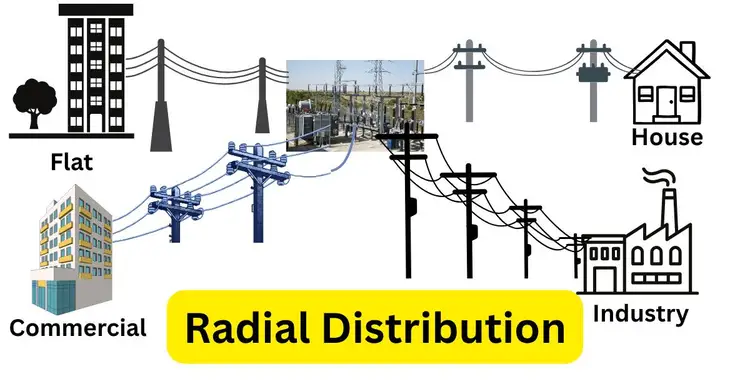
However, this straightforwardness has a major disadvantage. If a fault occurs on a primary branch, every customer downstream from that fault loses power until crews repair the line. To calculate the voltage drop at the end of a long radial feeder, engineers use a basic variation of Ohm’s Law:
Where $I$ is the current flowing through the line and $R$ is the total resistance of the line. Because voltage drops with distance, radial systems are only effective over relatively short distances unless utility companies install voltage regulators along the route.
Loop Distribution System
To address reliability issues with radial setups, utility companies often upgrade to a loop distribution system. Also known as a ring main system, this design creates a continuous loop of power lines that starts at the substation, travels through a service area, and returns to the same substation.
This layout provides two paths for electricity to reach any given customer on the loop. If a tree falls and breaks the line on one side, switches automatically isolate the damaged section. The power then reverses direction and flows to the customer from the other side of the loop.
The design costs slightly more than a radial system because it requires more cable and automated switching equipment. However, the massive reduction in power outage duration makes it a highly cost-effective upgrade for growing communities.
Network Distribution System
When a power outage simply is not an option, engineers build network distribution systems. This network consists of multiple substations interconnected in a grid.
If one substation fails or a major line breaks, the other sources instantly pick up the load. The transition happens so fast that your lights will not even flicker. This makes network systems the standard choice for densely populated urban centers, high-rise business districts, and critical facilities like hospitals.
Underground Distribution System
While overhead power lines dominate rural and suburban landscapes, underground distribution systems offer a distinct alternative. Instead of stringing wires across wooden or concrete poles, crews bury insulated cables in protective trenches or conduit pipes.
Burying wires underground protects them from bad weather. Underground cables are highly resistant to environmental outages as they are not affected by high winds, ice storms, or falling branches.
The primary disadvantage is cost. Trenching, laying conduit, and installing specialized ground-level transformers cost significantly more than erecting utility poles. Furthermore, when an underground cable does fail, finding and digging up the exact location of the fault takes much longer than spotting a broken wire on a pole.
Primary Distribution
Beyond the physical layout of the wires, we also classify distribution systems by their voltage levels. The primary distribution system acts as the bridge between the high-voltage transmission grid and the local neighborhood network.
When bulk power arrives at a local distribution substation, giant transformers step the transmission voltage down to a medium voltage. This primary distribution voltage typically ranges between 0.4 kilovolts (kV) and 33 kV.
Primary distribution lines act as the main arteries of the local grid. They carry this medium-voltage electricity out of the substation and transport it efficiently across town.
Secondary Distribution
The secondary distribution system handles the final leg of the electrical journey. Since the medium-voltage on primary lines is far too dangerous for household appliances, it must undergo one final reduction.
Distribution transformers—they step down the primary voltage to the utilization voltage. In North America or india, this is typically a 120/240 or 415/220-volt split-phase system for residential homes.
From the distribution transformer, the secondary distribution lines carry this low-voltage power directly to your property. A service drop cable connects these lines to the electrical meter attached to your house. This ensures that the moment you plug in a device, you receive a safe, steady, and precise flow of electricity, perfectly designed for human use.
Key Components and Their Role of Power Distribution
The electricity distribution system is a remarkable example of modern engineering. It draws electricity from the main transmission network and makes it safe for everyday use. To understand how a local grid works, we must understand each of its main physical components. Each component plays a specific, non-negotiable role in keeping your lights on and your business running.
Distribution Substations
When electricity finishes traveling across a high-tension transmission line at extreme voltages—often hundreds of thousands of volts—it is far too powerful to send down city streets.
The primary role of the distribution substation is to step down this massive voltage to a more manageable medium voltage. Inside the substation fence, you will find large power transformers that handle this heavy lifting. They drop the voltage to distribution levels, typically between 0.4 kilovolts (kV) and 33 kV.
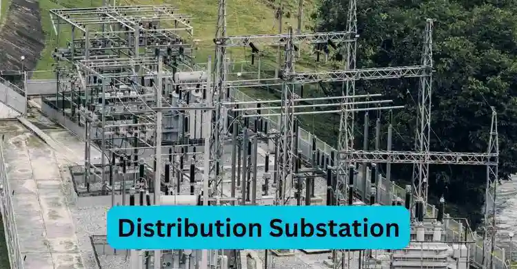
Beyond voltage reduction, substations serve as the protective hub for the entire local grid. They contain massive circuit breakers and protective relays. If a tree falls on a power line down the road, these protective devices instantly detect the spike in electrical current. They snap open in milliseconds, cutting off the power to prevent fires, protecting the equipment from catastrophic damage, and isolating the fault to a specific area.
Primary Distribution Lines
Once the substation reduces the voltage, the electricity needs a way to travel throughout the town. This is the job of the primary distribution lines. These feeder lines serve as the main arteries of your local power grid, carrying medium-voltage electricity from the substation to neighborhoods, industrial parks, and commercial districts.
Utility companies build primary distribution systems in two main ways:
- overhead and underground. Overhead primary lines are the most common. Utility teams transmit electricity through these bare or lightly insulated conductors and wooden, steel, or concrete poles.
- On the other hand, an underground line is laid beneath the ground, where power is safely transmitted via cables housed within conduit pipes. This distribution method is highly preferred in densely populated urban areas and modern residential colonies.
Distribution Transformers
While primary distribution lines carry electricity across town, their medium voltage remains far too dangerous to plug into a television or refrigerator. The grid requires one final pressure drop, and it is here that distribution transformers come into play.
You see these devices every day. They are mounted near the middle section of utility poles or placed on concrete pads in front of green homes and businesses.
The core function of a distribution transformer is to step down the primary medium voltage to a safe utilization voltage. To understand how a transformer changes voltage, we can look at the basic transformer turns-ratio formula.
Secondary Distribution Lines
After passing through the distribution transformer, the electricity enters the secondary distribution lines. These are the low-voltage wires that carry the final, stepped-down electricity directly toward homes and commercial buildings.
Secondary distribution lines operate at the exact voltage levels needed to run standard electrical equipment. In residential areas, this is typically a 220/415-volt. You will often see these lines running just a short distance from the pole-mounted transformer to the surrounding houses. Because they carry low voltage, they run lower on the utility pole than the primary lines to maintain safe clearances.
Service Drops
The final leg of the electrical journey is the service drop. This is the specific bundle of wires that connects the utility company’s secondary distribution lines directly to the consumer’s premises.
For an overhead system, the service drop is the insulated cable that spans the air from the nearest utility pole to the weatherhead on the side or roof of a house. In an underground system, it is the buried cable running from the green pad-mounted transformer directly to the side of the building.
The service drop terminates at the electricity meter. The meter acts as the formal handoff point between the utility company and the customer. It carefully measures the exact amount of electrical power flowing into the building for billing purposes. Once the electricity passes through this meter, it enters your home’s breaker panel, ready to safely power your appliances, lights, and devices the moment you need them.
Process of Power Distribution
As part of the electricity distribution process, vast quantities of electricity are drawn from the transmission grid and delivered with great care to the outlets embedded in the walls of your home. Let us look at exactly how this complex system functions every single second of the day.
Step-by-Step Flow of Electricity
The actual power distribution process begins when this high-voltage electricity reaches the outskirts of your town. Here is the sequence of events:
- The Distribution Substation: The electricity enters a local substation, which steps the extreme voltage down to a medium level, usually between 4,000 and 35,000 volts.
- Primary Distribution: The power travels through your town on primary distribution lines, either high up on utility poles or buried underground.
- Local Transformation: Before the power reaches your street, a distribution transformer drops the voltage one last time to a safe 120 or 240 volts.
- Secondary Distribution and Service Drop: The safe, low-voltage power moves along secondary distribution lines. A service drop wire then carries it directly to your electricity meter and into your home’s breaker panel.
Integration of Renewable Energy Sources
For over a century, the power distribution process was a one-way street. Electricity flowed from large power plants through the grid into homes. Today, the integration of renewable energy sources has completely changed how the system operates.
When you install solar panels on your roof, you do not just consume power; you generate it. If your solar panels produce more electricity than your home needs, the excess energy flows backward into the local grid. We call this bidirectional power flow.
Handling this two-way street requires major upgrades to traditional distribution networks. Utility companies are now utilizing smart grids equipped with modern sensors and automated switches. These smart systems constantly balance the load, ensuring that fluctuations in power from renewable energy sources like wind and solar do not overwhelm local transformers or cause voltage spikes. By integrating these clean energy sources, we create a more resilient, efficient, and environmentally friendly power grid.
Factors Influencing Power Distribution
Delivering electricity from a substation to your wall outlet is rarely a simple straight line. Utility companies must constantly adapt to a wide variety of physical, environmental, and technical variables.
Geographical Factors
Engineers face entirely different challenges when designing grids for dense urban centers compared to sprawling rural landscapes.
In urban areas, space is extremely limited. High population density means utility companies must deliver massive amounts of electricity into tight city blocks. To save space and improve safety, cities rely heavily on underground distribution systems. While these bury the visual clutter, they cost significantly more to install and maintain.
Conversely, rural areas present the challenge of distance. Homes and farms spread out over miles require long stretches of overhead primary distribution lines. As electricity travels these long distances, it naturally loses some of its pressure.
Load Demand
Not all electricity consumers are created equal. The type and size of the electrical load deeply impact how we structure the distribution grid. We generally divide these loads into three categories: industrial, commercial, and residential.
Industrial facilities, such as large manufacturing plants, demand substantial amounts of energy. They run heavy machinery that requires steady, high-capacity three-phase power. Because their load demand is so high, industrial customers often connect directly to primary distribution lines and use their own private step-down transformers.
Commercial and residential loads are much lighter but highly variable. A neighborhood’s power usage spikes in the morning when people wake up and in the evening when they return home. Managing these daily peaks and valleys is called load balancing. If a distribution system cannot handle a sudden spike in load demand, the local transformers can overheat, leading to localized blackouts.
Infrastructure
The physical health of the local grid plays a massive role in how well power flows. A power distribution system is only as strong as its weakest link. The quality and age of transformers, cables, and substations directly impact overall grid efficiency.
Aging infrastructure is a primary cause of power loss. Older transformers operate less efficiently, and degraded cables create higher electrical resistance. When electricity passes through a high-resistance load, a portion of that energy is wasted as heat. We calculate this power loss using the following formula:
Weather Conditions
Mother Nature poses the single greatest threat to power availability. Because the vast majority of our power distribution relies on overhead lines, severe weather is the primary cause of our power outages.
High winds can snap utility poles and blow tree branches directly into primary distribution lines, triggering immediate faults. In the winter, ice accumulation physically weighs down the cables until they snap. Even extreme summer heat waves create major distribution problems.
While underground distribution systems avoid wind and ice, they are not entirely weather-proof. Severe flooding can submerge underground vaults and short out pad-mounted transformers.
Technological Advancements
The traditional power grid is currently undergoing a massive transformation driven by new technologies. Historically, utility companies only knew the power was out when a customer called to complain. Today, technological advancements are turning static networks into highly responsive smart grids.
Smart grids rely on two-way communication. Automated sensors placed throughout the distribution lines instantly detect voltage drops or faults. If a line breaks, smart switches can automatically reroute electricity through a loop distribution system, restoring power to a neighborhood in seconds without any human intervention.
Furthermore, advanced technology allows the grid to handle decentralized power. With rooftop solar panels and home battery backups becoming common, automation software helps the distribution system safely manage bidirectional power flow.
Maintaining Power Availability and Reliability
For utility companies, maintaining power availability and reliability is the ultimate goal of any power distribution system. A reliable grid keeps hospitals saving lives, businesses running smoothly, and homes comfortable. To ensure uninterrupted power flow, engineers rely on a combination of rigorous maintenance routines, advanced technologies, and strategic energy management.
Preventive Maintenance
The best way to fix a power outage is to stop it before it happens. Preventive maintenance is the first line of defense in maintaining a reliable power distribution system. This proactive strategy involves the regular inspection, testing, and servicing of all grid components, including distribution transformers, primary and secondary lines, and substations.
Utility crews do not just look at utility poles; they use advanced diagnostic tools. For example, technicians use thermal imaging cameras to inspect distribution substations. A loose connection or a failing circuit breaker will generate excess heat before it breaks. Thermal cameras spot these hot spots early, allowing crews to repair the part before it triggers a blackout.
Additionally, crews routinely test the mineral oil inside large transformers. The oil functions as both a coolant and an insulator. By checking the oil for dissolved gases, engineers can detect internal degradation. Trimming trees near overhead primary distribution lines is another crucial, albeit low-tech, form of preventive maintenance. Keeping branches clear of wires removes the leading cause of weather-related power outages.
Fault Detection and Isolation
Modern power distribution systems rely heavily on smart grids and automated systems to handle emergencies. In the past, a single broken wire could knock out power to thousands of homes until a human operator physically found the break. Today, automated sensors instantly detect sudden spikes in electrical current that indicate a short circuit or fault.
Once the system detects a fault, automated reclosers and circuit breakers instantly snap open to isolate the damaged section.
Backup Systems
Sometimes, the primary power source from the transmission grid completely drops out. To maintain power availability during these major events, the distribution grid relies on robust backup systems.
For critical facilities like hospitals, data centers, and emergency response hubs, backup systems are legally required. These usually come in the form of heavy-duty diesel or natural gas generators that automatically kick on the moment the grid goes dark.
However, modern utility companies are increasingly turning to massive Battery Energy Storage Systems (BESS) at the substation level. These giant battery banks charge up during the day when renewable energy generation is high.
If a sudden fault drops the primary power supply, the battery systems instantly discharge, feeding electricity into the primary distribution lines. This keeps the lights on seamlessly while crews work to restore the main grid connection. If you’re looking for the best power backup solutions for your home, check out our article on Best Power Backup Options for Home
Load Balancing
Electricity is unique because it must be consumed the exact moment it is generated. Therefore, maintaining grid reliability requires constant load balancing. Utility companies must perfectly match the electricity supply with consumers’ real-time demand.
Power consumption fluctuates wildly throughout the day. Demand peaks in the late afternoon and early evening when people return home from work, turn on air conditioners, and cook dinner. If the load demand exceeds the capacity of the local distribution transformers, the equipment will overheat and fail.
To measure how efficiently a grid is managing its demand, engineers calculate the Load Factor. The formula is:
A higher load factor means the power usage is steady and efficient, while a lower load factor indicates extreme, stressful spikes in demand.
To improve the load factor and balance the grid, utilities use demand response programs. They offer financial incentives to industrial and residential customers who agree to reduce their power usage during peak hours. By shifting heavy energy use to off-peak times (such as running large machines or charging electric vehicles late at night), utility companies prevent grid overload, protect their transformers, and ensure steady, reliable power for everyone.
Operations of Power Distribution Systems
Utility companies do not just build the power grid and walk away. They actively operate it every single second of the day. This operational phase involves balancing supply and demand, protecting the infrastructure from unexpected faults, minimizing wasted energy, and adapting to new green technologies. Let us explore the critical day-to-day operations that keep our electrical grid functional and reliable.
Monitoring and Control
Operating a local power grid requires deep visibility into exactly what is happening across miles of physical wire. You cannot control what you cannot quantify. Therefore, monitoring and control form the central nervous system of modern power distribution systems.
Grid operators rely on real-time monitoring of voltage, current, and load demand. To achieve this, utility companies use a technology called SCADA (Supervisory Control and Data Acquisition). SCADA systems collect massive amounts of data from smart sensors placed on distribution transformers, primary lines, and substations.
To understand how operators measure the total power flowing through a specific line, we look at the basic power equation:
In this formula, Power (P) equals Voltage (V) multiplied by Current (I). By constantly monitoring both the voltage and the current, SCADA systems calculate the exact power load in real time. This ensures the electrical demand never exceeds the physical capacity of the distribution cables.
Protection Mechanisms
A crucial part of power distribution operations involves deploying strict protection mechanisms. These systems act as the grid’s immune system, instantly responding to hazards such as lightning strikes, fallen trees, or equipment failures.
The primary goal of these protective devices is to detect a fault and isolate it before it causes a fire or triggers a widespread blackout. The grid relies on three main lines of defense:
- Circuit Breakers: Located inside the distribution substations, these act as massive automated switches. When a sensor detects a sudden, massive spike in electrical current (a short circuit), the circuit breaker physically snaps open in milliseconds. This stops the flow of electricity to the damaged section of the grid. If you want to learn about circuit breakers, read our article on What is Circuit Breaker in Substation.
- Fuses: We use electric fuses on individual distribution transformers and smaller branch lines. Inside the fuse is a thin piece of metal designed to carry a specific amount of current. If the current exceeds that safe limit, the metal physically melts, breaking the circuit and stopping the power flow. If you want to learn about electric fuses, read our article on electric fuse working principle.
- Surge Protectors: When lightning strikes a main distribution line, a surge arrester immediately and safely diverts the excessive voltage into the ground, thereby preventing damage to sensitive equipment.
Energy Efficiency
Operating a power distribution system is not just about keeping the lights on; it is about delivering that power as efficiently as possible. When electricity travels through physical wires, a certain amount of that energy naturally converts into heat and dissipates into the air. We call these transmission line losses.
Utility companies spend significant operational resources to reduce these losses through advanced transformers and cables.
Integration of Distributed Energy Resources
Distributed Energy Resources (DERs) include rooftop solar panels, small wind turbines, and residential battery storage systems. When you install solar panels on your home, you become both a consumer and a generator of electricity. If your panels generate more power than your house needs on a sunny afternoon, that excess electricity flows backward into the local grid.
Challenges in Power Distribution
Delivering electricity safely and reliably to millions of homes is a massive engineering feat. However, power distribution systems face several ongoing challenges that utility operators must manage daily.
Voltage Drops and Power Losses
When electricity travels through physical wires, it naturally encounters resistance. This resistance creates two primary challenges for utility companies: voltage drops and power losses.
A voltage drop occurs when the electrical pressure decreases over long distances. If you live at the very end of a long rural distribution line, the voltage reaching your home might be lower than the voltage at the substation. We can calculate this drop using a basic variation of Ohm’s law:
Power loss is an even more expensive problem. As electrical current flows through the natural resistance of the distribution cables, some of that energy is converted to heat and escapes into the air. The formula for power loss highlights why this is such a major concern:
Maintenance and Fault Isolation
Maintaining a massive, sprawling network of utility poles, transformers, and underground cables is extremely difficult. The grid is constantly exposed to harsh weather, falling trees, and general equipment aging. When a physical component fails, a fault occurs, leading to power outages.
The biggest challenge in maintaining power reliability is fault isolation. Finding the exact location of that break often requires crews to physically drive down the line and inspect the wires by eye. By the time they locate the fault, isolate it, and make repairs, hours might have passed.
Integration of Renewable Energy and Bidirectional Power Flow
When your solar panels generate more electricity than your home consumes, that excess power flows backward into the distribution grid. We call this bidirectional power flow. The traditional grid infrastructure—especially older distribution transformers and protective relays—was simply not designed to handle power moving in reverse.
This two-way flow causes massive headaches for grid operators. It can create dangerous voltage spikes on local lines and mask fault currents, which prevents safety breakers from tripping when they should. Safely integrating renewable energy requires a complete overhaul of traditional grid management strategies.
Future Trends in Power Distribution
To overcome these physical and operational challenges, the power distribution industry is evolving rapidly. Engineers are deploying cutting-edge technologies to build a smarter, more resilient, and highly efficient grid. Here are the key trends shaping the future of how we deliver electricity.
Role of AI and IoT in Optimizing Distribution Systems
The Internet of Things (IoT) and Artificial Intelligence (AI) are fundamentally changing how utility companies operate. By placing smart IoT sensors on distribution transformers, power lines, and residential meters, grid operators collect massive amounts of real-time data.
AI helps perfectly balance load demand by automatically routing power to areas that need it most, ensuring the grid operates at peak efficiency during high-stress periods like summer heatwaves.
Decentralized Microgrids and Their Impact
The future of power distribution is moving away from massive, centralized grids toward decentralized microgrids. A microgrid is a localized power network that can operate independently from the main utility grid.
If a severe storm knocks out the main transmission lines, the microgrid simply disconnects—a process called “islanding”—and continues to supply power to its local users. This decentralized approach drastically reduces the impact of widespread blackouts and builds a much more resilient power infrastructure.
Innovations in Transformer and Cable Technologies
To address power losses and meet the complex demands of renewable energy, the grid’s physical infrastructure is undergoing a major upgrade. Solid-state transformers are beginning to replace traditional magnetic transformers. These digital devices not only step up and down the voltage but also actively manage bidirectional power flow, making solar integration seamless and safe.
We are also seeing massive innovations in cable technology. High-Temperature Superconducting (HTS) cables are slowly making their way into densely populated urban areas. These cables offer nearly zero electrical resistance. HTS cables can carry massive amounts of electricity in a fraction of the space, making them the ultimate solution for delivering power into crowded cities.
Conclusion
Power distribution systems form the critical final link in the long journey of electricity. They take massive amounts of raw energy and carefully refine it, ensuring it reaches your wall outlet safely and reliably. From basic overhead lines in rural towns to highly automated underground networks in major cities, this infrastructure has evolved tremendously over the past century.
However, as our energy demands grow and we transition heavily toward green, renewable power sources, the grid must continue to adapt. The old, one-way model of electricity delivery is no longer sufficient to support a modern society. By adopting modern solutions, we can transform our power distribution systems into highly efficient, fully reliable networks ready to power the next generation.
FAQ
What is a power distribution system?
A system delivering electricity from substations to consumers.
What are the main components?
Transformers, feeders, and distribution lines.
What are the types of distribution systems?
Radial, loop, and interconnected systems.
What is a radial distribution system?
A simple, one-directional power flow system.
What is a loop distribution system?
A system with multiple paths for power flow.
What is an interconnected system?
A network offering redundancy and reliability.
Why is voltage regulation important?
To ensure consistent power delivery to consumers.
How does a smart grid improve distribution?
By using technology for efficient power management.
What are common challenges in power distribution?
Power losses, outages, and maintenance issues.
I am an electrical engineer and also a blogger. I write informative blog posts on topics related to electrical and electronics engineering. If you are interested in these topics, you are welcome to my site to read these articles.