
Construction of Three Phase Induction Motor
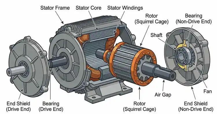
A three-phase induction motor is built from two mechanical assemblies and nothing more: a stationary stator and a rotating rotor. This article provides a detailed explanation of every physical component, the materials they are made of, and how they fit together. This article reflects my experience regarding the construction of induction motors, combining both theoretical knowledge and practical insights. During my training at the Jamalpur Railway Workshop, I conducted a detailed study of all the internal components of induction motors; the practical experience gained there in assembling and servicing electrical machines remains a cherished memory.
Main Parts of a Three Phase Induction Motor
Every motor comes down to a fixed set of components. The main parts of a three-phase induction motor are the frame, the stator core, the stator winding, the rotor (squirrel cage or wound), the shaft, the bearings, the end shields, and the air gap between the stator and rotor. You will learn about all of this in detail later in this article.
The Two Core Assemblies — Stator and Rotor
Two assemblies. One machine. The stator is the stationary outer assembly that stays fixed in place. The rotor is the rotating inner assembly that spins inside it. Between the two sits the air gap — a precise mechanical clearance, typically 0.4 to 4 mm depending on motor size. Every other part serves one of these two assemblies.
Stator Construction
The stator is the stationary heart of the motor, assembled from three distinct parts. Each is built for a specific mechanical or magnetic purpose: the frame gives the motor its body, the stator core carries the magnetic path, and the stator winding holds the conductors. Together they form the fixed outer structure. It is further explained what the function of each part is and how it is made.
Stator Frame
The frame is the outer body of the motor. The frame is the motor’s outer housing, not the stator, and the two are entirely separate components. Its construction depends on motor size and duty: cast iron for standard industrial units, cast aluminum for lighter machines, or fabricated steel for large ratings. The frame houses and protects the stator core and winding, supports the entire assembly, and carries the mounting feet and cooling fins.
Stator Core
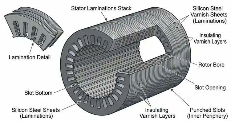
The stator core carries the magnetic path through the machine. It is built from thin, high-grade silicon steel laminations, each around 0.35 to 0.5 mm thick, stacked together and insulated from one another. The reason is direct: stacked laminations reduce eddy-current losses that a solid core would generate. Slots are punched into the inner periphery of the core, and these slots hold the stator winding in place.
Stator Winding
The winding sits inside the stator slots. It is made from insulated copper conductors, wound as a three-phase winding in either a double-layer or single-layer arrangement, and connected in star or delta. The insulation matters here — Class B or Class F insulation is common, chosen to withstand operating temperatures. The three-phase windings are spaced physically apart around the core, each occupying its own set of slots.
Rotor Construction
The rotor is the moving heart of the machine. Mounted on the shaft and separated from the stator by the air gap, it is the assembly that actually turns. Its construction comes in two forms — and this is the single most important structural choice in the entire motor. The two builds are the squirrel cage rotor and the wound, or slip ring, rotor. Both share the same laminated core. The main difference lies in the method of conductor connection.
Squirrel Cage Rotor
The most rugged rotor build there is. The squirrel cage rotor starts with a laminated cylindrical core, with slots cut into its outer surface. Each slot holds a solid conductor bar of copper or aluminum — no coils, no windings, just bars. These bars are permanently short-circuited at both ends by conducting end rings.
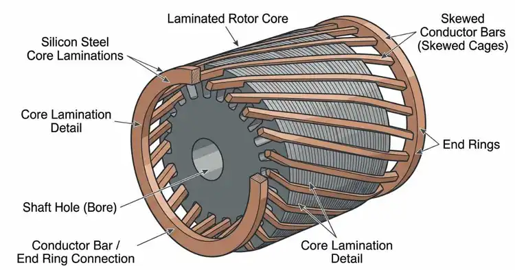
The bar-and-ring assembly forms a shape that resembles a cage, and that shape gives the rotor its name. The bars are often skewed — set at a slight angle rather than straight along the core — to cut down noise and reduce cogging. Make no mistake: this rotor has no wound coils and no external connections. It is a sealed, self-contained conductor cage.
Wound Rotor (Slip Ring Rotor)
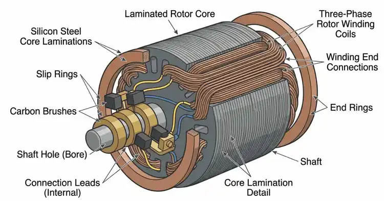
The connectable rotor build. The wound rotor, also called the slip ring rotor, uses a laminated slotted core that carries a three-phase copper winding, wound for the same number of poles as the stator. The three ends of this winding are brought out to three slip rings mounted on the shaft.
The carbon brushes rest on these rings and give you the external connection you won’t find in a squirrel cage design. The materials are specific: a copper winding on the core, copper or brass slip rings on the shaft, and carbon brushes riding against them. That is the full hardware — a wound rotor built to be connected.
If you want to explore this type of motor in more depth, you can read our detailed article on the Slip Ring Induction Motor.
Squirrel Cage Rotor vs Wound Rotor — Construction Compared
Same job. Two entirely different builds. The table below sets out the physical construction of each rotor side by side.
| Construction Feature | Squirrel Cage Rotor | Wound Rotor (Slip Ring Rotor) |
| Rotor core | Laminated cylindrical core with slots on the outer surface | Laminated slotted core |
| Conductor type | Solid copper or aluminum bars | Three-phase copper winding |
| Conductor connection | Bars short-circuited at both ends by end rings | Winding ends brought out through the shaft |
| External connections | None — sealed and self-contained | Three winding ends connected externally |
| Slip rings and brushes | Absent | Three slip rings with carbon brushes |
| Complexity | Simple, few parts | Complex, more parts to assemble and service |
| Typical material cost | Lower | Higher |
The structural difference comes down to one line: the squirrel cage is a sealed, self-contained conductor cage, while the wound rotor is a connectable three-phase winding brought out through slip rings.
Shaft, Bearings, and End Shields
The rotor cannot spin without a support structure engineered to hold it true. Three mechanical parts carry that load — the shaft, the bearings, and the end shields. Each is built for strength, precision, and alignment. Here is how they come together.
Shaft
The shaft is the mechanical spine of the motor. It is machined from high-carbon or alloy steel, ground for strength and precise concentricity so the rotor spins without wobble. The shaft carries the rotor core along its length and transmits the mechanical output — the torque — straight to the connected load. Every bit of work the motor produces travels out through this single steel rod.
Bearings
Bearings support the shaft and let it turn smoothly, one seated at each end shield. The type depends on the load. In standard motors with moderate loads, ball bearings manage everyday general-duty rotation. Roller bearings take over in machines that carry heavy radial loads, spreading the force across a larger contact surface. Both reduce friction between the rotating shaft and the fixed frame, keeping the rotor turning cleanly for years.
End Shields (End Brackets)
The end shields close the frame at both ends and house the bearings. They are cast from iron or aluminum and bolted directly to the frame, then machined to hold the bearings in precise alignment with the stator bore. That precision does one critical job: it locks the rotor centered within the stator and maintains a uniform air gap all the way around. Get this alignment wrong, and the gap distorts. Get it right, and the rotor runs true.
The Air Gap
Small dimension. Massive consequence. The air gap is the narrow, uniform mechanical clearance between the stator bore and the rotor surface — typically 0.4 to 4 mm, depending on motor size. It is the single tightest tolerance in the entire build.
Uniformity is not optional. That clearance must stay small and perfectly even all the way around the rotor. An uneven gap throws the rotor off-center, and the result is immediate: vibration, noise, and mechanical rubbing between the rotor surface and the stator bore. Keep the gap uniform, and the rotor spins clean.
Materials Used in a Three Phase Induction Motor
Every part earns its material. The construction of a three phase induction motor pairs each component with a metal chosen for its exact mechanical or electrical job — nothing is arbitrary. Here is the full material map, part by part:
- Frame: Cast iron, aluminum, or fabricated steel, selected by motor size and duty.
- Stator and rotor cores: Thin silicon steel laminations, stacked and insulated.
- Stator winding: Insulated copper conductors.
- Squirrel cage bars and end rings: Copper or aluminum.
- Wound rotor winding: Copper.
- Slip rings: Copper or brass.
- Brushes: Carbon.
- Shaft: Alloy steel or high-carbon steel.
- Bearings: Hardened steel.
- End shields: Cast iron or aluminum.
Match the material to the part, and the induction motor holds up for years. That pairing — copper for conduction, silicon steel for the core, hardened steel for the load — is the specification that defines a well-built machine.
Conclusion
Two assemblies. One durable machine. A three-phase induction motor is built from a stationary stator and a rotating rotor, with a shaft carried on bearings inside sealed end shields and a precise air gap holding the two apart. That rugged construction is exactly why the motor survives decades of continuous industrial duty without failing.
Frequently Asked Questions
What are the two main parts of a three phase induction motor?
A three phase induction motor has two main parts: the stationary stator and the rotating rotor. The stator stays fixed; the rotor spins inside it. Supporting these two core assemblies are the frame, the shaft, the bearings, and the end shields, which together hold the rotor centered and turning true.
Why is the stator core made of laminations?
The stator core is built from thin, high-grade silicon steel laminations, each around 0.35 to 0.5 mm thick, stacked and insulated from one another. The reason is direct: stacked laminations reduce eddy-current losses that a solid steel core would generate. Less loss means less wasted heat and a cooler, more efficient machine.
What is the difference in construction between a squirrel cage rotor and a wound rotor?
The construction differs entirely in the conductors. The squirrel cage rotor uses solid copper or aluminum bars, permanently short-circuited by end rings, with no external connections. The wound rotor uses a three-phase copper winding brought out through slip rings and carbon brushes. One is a sealed cage; the other is a connectable winding.
What material is used for the rotor bars?
The rotor bars in a squirrel cage induction motor are made of copper or aluminum. Copper offers higher conductivity; aluminum lowers cost and weight. These solid bars sit in the rotor slots and are permanently short-circuited at both ends by end rings made of the same material, forming a single cage.
How wide is the air gap in a three phase induction motor?
The air gap is the small mechanical clearance between the stator bore and the rotor surface, typically 0.4 to 4 mm depending on motor size. It must stay small and perfectly uniform all the way around. An uneven gap throws the rotor off-center, causing vibration, noise, and mechanical rubbing.

I am an electrical engineer and also a blogger. I write informative blog posts on topics related to electrical and electronics engineering. If you are interested in these topics, you are welcome to my site to read these articles.