Working Principle of Three Phase Induction Motor
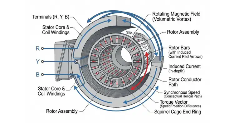
One field. One motion. A three-phase induction motor turns because a rotating magnetic field sweeps through it and drags the rotor along. This article breaks down the working principle step by step — how that field forms, how current appears in the rotor, and how torque pulls it into motion. In this article, I have shared my practical experience alongside the theory, explaining it in clear and simple language.
How Does a Three Phase Induction Motor Work?
A three-phase induction motor works in one clean chain. A three-phase supply energizes the stationary winding and creates a rotating magnetic field. That field induces current in the rotor, and the interaction between the two produces torque — which turns the rotor. Further in this article, you will understand each step in detail. For the physical build of the stator, rotor, and every internal part, read our guide on the construction of a three-phase induction motor.
Step 1 — How the Rotating Magnetic Field Is Produced
The rotating magnetic field makes everything else possible. Without it, nothing turns.
Here is how it forms. When a three-phase AC supply energizes the stator winding, the three phases do not peak at the same instant — they peak in sequence, one after another. Each phase produces its own magnetic effect, and because they rise and fall in a fixed order, their combined result is a single magnetic field that does not sit still. It rotates. This resultant field sweeps around the stator at a fixed, steady speed.
That speed has a name: synchronous speed. Three separate currents, one continuous rotating field — that is the heart of how an induction motor works.
The Synchronous Speed Formula
The synchronous speed is fixed by two things: supply frequency and the number of poles. The formula states it directly:
Ns = 120f / P
- Ns — synchronous speed, in RPM (revolutions per minute)
- f — supply frequency, in Hz
- P — number of poles
Run the numbers on a common case. A 4-pole motor on a 50 Hz supply:
Ns = (120 × 50) / 4 = 1500 RPM
The rotating magnetic field turns at 1500 RPM. Remember one thing here — this is the speed of the field, not the speed of the rotor. The rotor runs slightly below it. That gap matters, and it comes into play later.
Step 2 — How Current Is Induced in the Rotor (Faraday’s Law)
The rotor carries no direct supply. No power line feeds it. Yet current still flows through it — and that current is induced.
Understand this sequence carefully. The rotating magnetic field sweeps past the rotor conductors, cutting across them at a relative velocity — the speed difference between the field and the rotor. By Faraday’s law of electromagnetic induction, whenever a conductor cuts through a changing magnetic field at relative velocity, an electromotive force (EMF) is induced across that conductor. The rotor conductors form a closed circuit. So the induced EMF drives a current through them.
No supply enters the rotor. The field does the work. That is electromagnetic induction in action, and it is the event that brings the rotor to life.
Why the Rotor Needs No External Supply
The rotor is energized entirely by induction from the stator field. No wires run to it. No brushes touch it. No external connection feeds it power. The rotating magnetic field cuts the rotor conductors, Faraday’s law induces an EMF, and rotor current flows through the closed circuit on its own. Cut off from any supply, the rotor still carries current — because the field puts it there.
Step 3 — How Torque Is Produced (Lenz’s Law)
Induced current alone does not turn a motor. Interaction does.
The current now flowing in the rotor creates its own magnetic field. This rotor field meets the stator’s rotating magnetic field, and the two interact. Lenz’s law governs what happens next: the induced rotor current always opposes the change that created it. That change is the relative motion between the rotor and the rotating field. To oppose it, the rotor is forced to chase the field — it starts rotating in the same direction, trying to catch up and cancel the relative motion.
That chase is the torque. The rotor turns, and the motor runs.
Why the Rotor Can Never Reach Synchronous Speed
Here is the hard rule: the rotor always runs slightly below synchronous speed. It can never match it.
Follow the logic, and you will see why. If the rotor ever caught the rotating magnetic field and spun at the same speed, the two would move together as one. No relative motion. No magnetic flux cutting the rotor conductors. No changing magnetic field, so no induced EMF. No EMF means no rotor current — and no current means no torque. The moment torque disappears, the rotor slows down. And the instant it slows, relative motion returns, flux cuts the conductors again, current flows, and torque revives.
The rotor is trapped in a chase it can never win. That gap between field speed and rotor speed is not a defect. It is the exact condition that keeps the motor turning. Close the gap completely, and the motor stops driving itself.
That gap has a name. Engineers call it slip.
What Is Slip in a Three Phase Induction Motor?
Slip is the difference between the synchronous speed of the rotating magnetic field and the actual speed of the rotor, expressed as a percentage. The formula states it directly:
s = (Ns − N) / Ns × 100%
- s — slip, expressed as a percentage
- Ns — synchronous speed, in RPM
- N — actual rotor speed, in RPM
Under normal running conditions, slip stays small. A three phase induction motor typically runs with a full-load slip of around 2 to 5 percent. That narrow margin is enough to keep the rotor lagging just behind the field.
And that lag is the whole point. Slip is the quantity that guarantees relative motion between the rotor and the rotating field — and relative motion is what induces current and produces torque. No slip, no torque. The small gap you might dismiss as inefficiency is the mechanism that makes the motor work at all.
How to calculate slip using a quick example
Put the formula to work with the same motor from earlier — a 4-pole machine on a 50 Hz supply, with a synchronous speed of 1500 RPM. Say the rotor turns at 1440 RPM under load.
Substitute the values:
s = (1500 − 1440) / 1500 × 100%
s = 60 / 1500 × 100%
s = 0.04 × 100% = 4%
The rotor runs at 4 percent slip — squarely inside the typical 2 to 5 percent range. The field turns at 1500 RPM, the rotor follows at 1440 RPM, and that 60 RPM difference is exactly what keeps the torque flowing.
The Complete Working Sequence — Start to Rotation
Six steps. One continuous chain. This is the three phase induction motor working principle stripped to its bare mechanism — every stage that turns a three-phase alternating current supply into a spinning shaft:
- The three-phase supply energizes the stator winding.
- A rotating magnetic field forms and turns at synchronous speed.
- The field cuts the rotor conductors at relative velocity.
- Faraday’s law induces an EMF and current in the rotor.
- Lenz’s law forces the rotor to oppose the relative motion.
- Torque is produced, and the rotor rotates just below synchronous speed.
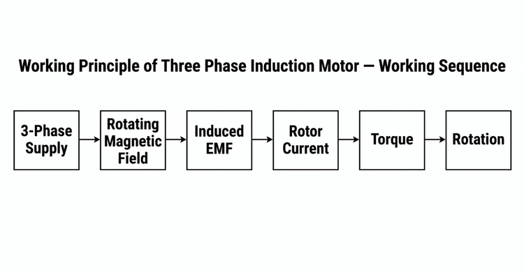
By observing the entire process, you will understand the complete mechanism. Supply in, field forms, current induced, torque delivered, rotor turning. That is how an induction motor works — start to rotation.
Conclusion
One mechanism drives it all. A three-phase supply builds a rotating magnetic field, that field induces current in the rotor, and the interaction produces torque that turns the rotor just below synchronous speed. No external supply to the rotor. No starting device. Just electromagnetic induction doing the work. That single chain is why the three phase induction motor drives most of the world’s industrial equipment — pumps, fans, conveyors, and heavy machinery running around the clock on the same clean principle.
Frequently Asked Questions
How does a three phase induction motor work in simple words?
A three phase induction motor works in one clean chain. The stator winding creates a rotating magnetic field. That field sweeps past the rotor and induces current in it. The induced current interacts with the field, producing torque that turns the rotor — spinning it just below synchronous speed.
Why is a three phase induction motor self-starting?
The moment the stator connects to a three-phase supply, the rotating magnetic field forms instantly. That field immediately induces current in the rotor and produces torque — no external starting device needed. The motor turns on its own.
What is slip and why is it necessary?
Slip is the difference between synchronous speed and actual rotor speed, expressed as a percentage: s = (Ns − N) / Ns × 100%. It typically runs 2 to 5 percent at full load. Slip is necessary because it guarantees the relative motion between rotor and field that produces torque. No slip, no torque.
Why can’t the rotor spin as fast as the magnetic field?
At synchronous speed, the rotor and the rotating magnetic field would move together. No relative motion means no flux cutting the conductors, no induced EMF, no current, and no torque. Without torque, the rotor slows. So it must always lag behind the field to keep running.
What role do Faraday’s law and Lenz’s law play?
Faraday’s law explains how the rotating magnetic field induces an EMF and current in the rotor as it cuts across the conductors. Lenz’s law explains why that induced current produces torque — the rotor opposes the relative motion and chases the field, turning in the same direction to run the motor.

I am an electrical engineer and also a blogger. I write informative blog posts on topics related to electrical and electronics engineering. If you are interested in these topics, you are welcome to my site to read these articles.