What are The Losses in Transmission Line
Transmission lines serve as the vital highways of our electrical power systems, safely carrying electricity from power plants directly to our homes and businesses. Without these networks, modern life would simply come to a standstill. However, transferring electricity over long distances is rarely perfect, and some energy naturally slips away along the journey. Understanding why this happens is essential for improving grid efficiency, lowering energy costs, and ensuring a reliable power supply for everyone.
So, what exactly happens to this lost power? In this article, we will explore the core concepts of energy dissipation in our power grids. We will clearly define what transmission line losses are, examine the different types and their root causes, and discuss the most effective ways to reduce them. Let’s dive in and see how we can keep our electrical systems running smoothly and efficiently.
What are Transmission Line Losses
When electricity travels from a power plant to your home, it must cover vast distances. During this long journey through electrical transmission systems, some of the generated energy vanishes before it reaches its destination. We define this reduction in delivered energy as transmission line losses.
To put it simply, power loss occurs because the cables and equipment used to transmit electricity are not perfect. As electric current flows through metal wires, it encounters electrical resistance at every point. This natural resistance converts a portion of the valuable electrical energy into heat, which then safely dissipates into the surrounding air. In the utility industry, experts often refer to this everyday physical phenomenon as line loss.
These electrical losses are a standard part of moving high-voltage current across any grid. However, keeping them as low as possible is incredibly important for energy conservation. When a grid wastes less energy along its route, it achieves higher transmission efficiency. A highly efficient network means lower operating costs for utility companies and cheaper electricity bills for you. By understanding exactly how and why this energy slips away, engineers can design stronger, smarter networks to deliver power right where we need it most.
Types of Losses in Transmission Lines
Electricity transmission losses within the power grid are categorized into two main types: technical and non-technical. Understanding these two categories helps utility companies improve overall transmission efficiency and keep their energy costs low.
Technical Losses
Electric current and its effects, such as heat generation and electromagnetic interference, play a significant role in transmission line losses.Technical losses occur naturally due to the physical properties of the materials used in the power grid. Even the best materials cannot perfectly transfer electricity. When current flows through wires, transformers, and other equipment, a portion of it is converted to heat or absorbed by the surrounding environment.
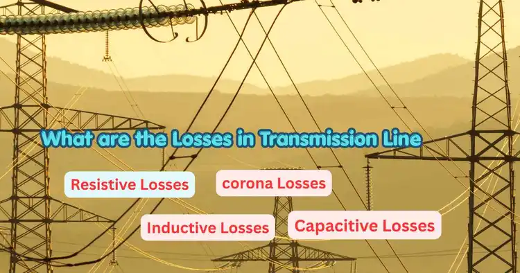
The main subcategories of technical losses are:
- Resistive Losses (I²R Losses): This is the most common type of loss in a high voltage power line. Every metal wire has a natural opposition to the flow of electricity, known as line resistance. As the current passes through the wire, this resistance dissipates energy directly in the conductors, turning some of the electricity into heat.
- Corona Losses: When carrying massive amounts of electricity, high-tension transmission lines can ionize the air surrounding them. It creates a faint glow and a buzzing sound known as corona discharge. This chemical and physical reaction pulls energy straight from the wire, resulting in a steady loss of power.
- Dielectric Losses: Power cables, especially those buried underground, use thick insulation to contain current safely. However, alternating current can cause the insulating material to heat up over time. We call this energy loss dielectric loss, and it reduces the usable power that reaches the end of the line.
- Inductive and Capacitive Losses: Alternating current creates shifting magnetic and electrical fields around the wires. These fields interact with the grid’s physical structure, creating inductive and capacitive reactance. While these forces do not directly consume energy as resistance does, they force the grid to push extra current to maintain stability, ultimately increasing the total energy lost along the route.
Non-Technical Losses
While technical issues relate to physics, non-technical losses occur due to human actions or equipment failures outside of the normal electrical flow. These losses mean power reaches its destination but goes unrecorded or unpaid.
The primary causes of non-technical losses include:
- Theft of Electricity: Some individuals illegally tap into power lines or bypass their meters to use electricity without paying. It creates a heavy, unrecorded burden on the grid.
- Metering Inaccuracies: Sometimes, the problem is simply faulty equipment. Old, broken, or improperly calibrated electric meters can fail to measure the correct amount of power a home or business uses.
Engineers are constantly engaged in identifying and resolving technical and non-technical challenges, striving to build smarter, more reliable electrical networks to ensure everyone receives dependable electricity.
How to Calculate Transmission Line Losses
How to Calculate Transmission Line Losses Step-by-Step
Every year, power grids lose Crores of rupees worth of electricity simply moving current from point A to point B. If you want to build or manage an efficient power system, you must know exactly how much energy vanishes along the way. Figuring out this lost energy helps engineers design smarter grids and helps utility companies keep electricity bills low.
Here, you will learn how to calculate losses in a transmission line. You will also discover why these calculations are essential, which key mathematical formulas you will need, what each variable represents, and how to apply them in real-world scenarios.
Why Calculating Transmission Line Losses Matters
Before we look at the math, we need to understand why we do it. Calculating power transmission losses serves several vital purposes in electrical engineering and grid management.
- First, it determines the grid’s efficiency. When you know precisely how much power is generated at the plant and how much reaches the destination, you gain a clear understanding of the overall health of your network. High losses indicate that the system is highly inefficient, resulting in a wastage of both fuel and money.
- Secondly, precise calculations serve as a guide in selecting equipment. If engineers install cables based on guesswork—without accurately calculating power losses—two scenarios may arise. First, the cables or wires used to handle the electrical load may prove to be too thin. Consequently, the cables carry a current exceeding their capacity, causing them to overheat and resulting in significant energy waste. Second, if excessively heavy cables or wires are used, the infrastructure can sustain damage, and even hazardous power outages may occur.
Finally, calculating line loss helps experts choose the right voltage level. By running the numbers, utility companies can see mathematically that increasing the voltage significantly reduces wasted energy, allowing them to optimize the entire transmission route.
The Basic Formula for Transmission Line Losses
When electricity flows through a metal conductor, the material naturally resists the current. This physical resistance turns a portion of the electrical energy into heat. Engineering refers to this as resistive loss. Because it represents the largest portion of technical power loss in a transmission system, it is the primary focus of our calculations.
The fundamental mathematical expression for finding power loss in a single-phase circuit is the I-squared R formula:
Ploss = I² × R
Understanding the Variables
To use this formula correctly, you need to understand what each letter represents:
- Ploss (Power Loss): This is the total amount of electrical energy wasted as heat. We measure this value in Watts (W) or Kilowatts (kW).
- I (Current): This represents the flow of electricity moving through the transmission line. We measure electrical current in Amperes, commonly called Amps (A). Because this value is squared in the formula, even a small increase in current causes a massive increase in power loss.
- R (Resistance): This is the natural opposition the wire provides against the flowing electricity. We measure resistance in Ohms (Ω). The resistance depends on the length of the wire, its thickness, and the material it is made of (like copper or aluminum).
Advanced Formulas for 3-Phase Systems
Most modern high-voltage transmission lines do not use single-phase power. Instead, they use three-phase alternating current (AC) systems to efficiently deliver large amounts of energy.
Because a three-phase system uses three separate conductors, we must adjust our basic formula to account for all three. The formula for total power loss in a 3-phase transmission line becomes:
Ploss = 3 × I² × R
However, you rarely know the exact current (I) right from the start. Usually, a utility company only knows the total Power (P) they want to send, the Voltage (V) of the line, and a metric called the Power Factor.
To find the current, you must use this formula first:
I = P / (√3 × V × cosΦ)
Here is what the new variables mean:
- P (Total Power): The actual power transmitted, usually measured in Watts or Megawatts (MW).
- V (Voltage): The line-to-line voltage pushing the current, measured in Volts (V) or Kilovolts (kV).
- cosΦ (Power Factor): A ratio showing how effectively the system uses electrical power. A perfect system has a power factor of 1.0, but real-world systems usually sit between 0.8 and 0.95.
- √3 (Square Root of 3): A constant value (approximately 1.732) required for three-phase system.
Step-by-Step Guide to Calculating Power Loss
Now that you know the formulas, you can calculate the transmission line losses for any network. Follow these sequential steps to get an accurate result.
- Identify the total power demand: Determine how much actual power (P) the transmission line needs to deliver. Convert this number into standard Watts.
- Note the transmission voltage: Find the line voltage (V) and convert it into standard Volts.
- Determine the power factor: Check the system specifications for the power factor (cosΦ).
- Calculate the line current: Plug your power, voltage, and power factor into the 3-phase current formula to find the exact Amps flowing through the line.
- Find the line resistance: Check the manufacturer specs for the cable’s resistance per kilometer, then multiply it by the total length of the transmission line to get total resistance (R).
- Compute the total power loss: Plug your calculated current (I) and total resistance (R) into the 3-phase power loss formula (3 × I² × R).
Practical Example of Calculating Line Loss
Let us put the math to work with a real-world scenario. Imagine a utility company needs to transmit 100 Megawatts of power over a three-phase transmission line.
Here are our known variables:
- Total Power (P) = 100 MW (which is 100,000,000 Watts)
- Line Voltage (V) = 220 kV (which is 220,000 Volts)
- Power Factor (cosΦ) = 0.9
- Resistance per phase (R) = 5 Ohms
Step 1: Calculate the Current (I)
First, we find the current using our formula: I = P / (√3 × V × cosΦ)
- I = 100,000,000 / (1.732 × 220,000 × 0.9)
- I = 100,000,000 / 342,936
- I = 291.6 Amps
Step 2: Calculate the Power Loss (Ploss)
Next, we plug the current into our 3-phase loss formula: Ploss = 3 × I² × R
- Ploss = 3 × (291.6)² × 5
- Ploss = 3 × 85,030.56 × 5
- Ploss = 1,275,458 Watts
Step 3: Analyze the Results
The total transmission line loss is 1,275,458 Watts, or roughly 1.27 Megawatts.
To find the percentage of power lost, we divide the loss by the total power and multiply by 100.
- (1.27 MW / 100 MW) × 100 = 1.27%
In this scenario, the utility company loses 1.27% of its generated power simply moving it through the cables.
How Voltage Impacts Transmission Losses
Looking closely at the mathematical expressions reveals a crucial secret about electrical grids. Because current (I) is squared in the power loss formula, keeping the current as low as possible is the best way to prevent energy waste.
How do you lower the current while delivering the same amount of power? You increase the voltage.
If you look at the current formula [I = P / (√3 × V × cosΦ)], you can see that voltage sits at the bottom of the fraction. As voltage goes up, but same time current goes down. If you double the voltage on a transmission line, you cut the current in half. Because the power loss formula squares the current, cutting the current in half actually reduces your power losses to just one-quarter of their original amount.
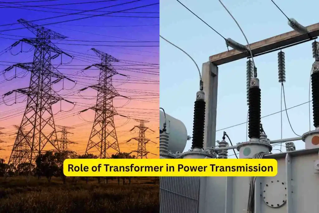
This simple mathematical relationship explains exactly why utility companies use massive transformers to push electricity to 220 kV, 400 kV, or even higher before sending it across long distances. High voltage equals low current, and low current equals minimal power loss.
Transmission Line Losses Solution
Calculating losses within transmission lines constitutes the first step toward establishing a more efficient and reliable electrical network. By understanding the interplay among current, voltage, and physical resistance, engineers can make more informed decisions.
In future projects, to mitigate these calculated losses, engineers consider various measures, such as using thicker conductors to reduce physical resistance, upgrading transformers to increase transmission voltage, and installing capacitor banks to improve the system’s overall power factor.
What Causes Power Loss in Transmission Lines?
You might be surprised to learn that a significant chunk of generated electricity never actually reaches your wall outlet. As electricity travels from massive power plants to local neighborhoods, a portion of that valuable energy simply vanishes along the way.
Understanding the root causes behind power loss in transmission lines is the first step toward building a better, smarter grid. When engineers pinpoint exactly why energy escapes, they can design targeted solutions to stop it. Fixing these leaks ultimately boosts transmission efficiency, reduces fossil fuel waste at the generation plant, and keeps your monthly electricity bills from climbing.
To understand this major engineering challenge, the causes of power loss are broadly categorized into two main groups: technical causes and non-technical causes. Within this framework, you will explore in detail the specific factors responsible for the wastage of electricity within our power networks.
Technical Causes of Electrical Losses
Technical losses occur naturally due to the physical rules of electricity. The components of overhead transmission lines, such as conductors and insulators, significantly influence high-tension transmission line losses. Even if a utility company uses the absolute best equipment available, some level of energy waste is physically unavoidable.
Here are the primary technical causes of power loss in transmission lines:
1. High Line Resistance
You might think utility companies simply turn on the power plant closest to a city to save energy. However, power grids are massive webs connecting dozens of power plants to hundreds of cities simultaneously.
Calculating the transmission line loss coefficient is essential for a process called “economic dispatch.” Economic dispatch is how grid operators decide which power plants should produce electricity at any given moment. Their goal is to meet the public’s energy demand at the lowest possible cost.
2. Corona Discharge
When utility companies transport power over long distances, they use incredibly high voltages. Sometimes, this extreme voltage overpowers the natural insulating properties of the surrounding air.
When the voltage exceeds the air’s breakdown strength, the air molecules around the wire become ionized. This creates a faint, glowing violet halo and a distinct buzzing sound known as corona discharge. This physical and chemical reaction essentially extracts electrical energy from the conductor’s surface and dissipates it into the atmosphere. Humid weather and rough conductor surfaces make this effect much worse.
3. Dielectric Absorption
Many power lines, especially those buried underground, require thick layers of plastic or rubber insulation to contain the electricity. However, alternating current (AC) reverses direction rapidly.
This constant shifting forces the molecules within the insulating material to rapidly realign. All this molecular movement generates friction, which heats the insulation. The energy required to heat that insulation comes directly from the transmission line. Engineers refer to this specific cause of energy waste as dielectric loss.
4. Inductive and Capacitive Reactance
Because transmission lines use alternating current, they constantly generate expanding and collapsing magnetic and electric fields around the cables.
Creating and maintaining these fields requires energy. While these electromagnetic forces do not burn up power in the same way simple resistance does, they create opposing forces called inductive and capacitive reactance. These forces cause the voltage and current to become out of sync. When the grid falls out of sync, the utility company must push extra current through the lines just to deliver the same amount of usable power, which, in turn, skyrockets the system’s total heat losses.
Environmental Factors Causing Power Loss
Physics and equipment are not the only factors affecting transmission efficiency. Mother Nature also plays a massive role in how much energy reaches its final destination.
5. Extreme Temperatures
Heat is the enemy of electrical transmission. As the ambient temperature rises on a hot summer day, the metal conductors expand. This physical expansion actually increases the wire’s natural line resistance. Higher resistance leads to more energy dissipation as heat, which makes the wire even hotter. This compounding effect causes grid efficiency to plummet during massive heat waves.
6. Severe Weather Conditions
Rain, fog, and snow dramatically change how electricity behaves. Moisture in the air makes it much easier for current to ionize the atmosphere, triggering a massive increase in corona discharge. Additionally, strong winds can blow debris onto the lines or push them too close together, causing minor power outages and electrical arcs.
Non-Technical Causes of Electrical Losses
While technical losses stem from physics and weather, non-technical losses come from human behavior and administrative errors. In these cases, the electricity safely reaches its destination, but the utility company cannot track, bill, or account for it.
7. Electricity Theft
In many parts of the world, unauthorized users illegally tap directly into power lines to steal electricity. They bypass the safety equipment and draw massive amounts of unrecorded current. Because the utility company cannot monitor this stolen load, it puts severe physical strain on the grid, leading to blown transformers and increased heat losses throughout the entire local network.
8. Metering Inaccuracies
Sometimes, the cause of power loss is simply a broken clock. Every home and business relies on a meter to track electricity usage. However, older mechanical meters degrade over time. Dust, rust, and worn-out gears can cause a meter to spin slower than it should. When a meter underreports the amount of power consumed, the unregistered electricity becomes a non-technical loss for the grid operator.
What Are Transmission Line Loss Coefficients?
Have you ever wondered how grid operators decide which power plant should generate your electricity? It all comes down to complex math and a deep understanding of electrical losses. When sending power across vast distances, energy dissipation is physically inevitable.
To manage this unavoidable waste, engineers use a specific metric known as the transmission line loss coefficient.
Here, you will learn in detail what these coefficients actually are and why they hold such immense significance in our daily lives. You will also discover how grid operators calculate this critical factor regarding electricity loss. Finally, we will examine real-world examples that demonstrate how these figures directly improve transmission efficiency.
Understanding the Transmission Line Loss Coefficient
Moving electricity from a power plant to your neighborhood is not free. As current flows through metal wires, the wire’s resistance converts some of that electrical energy into heat. We call this process energy dissipation.
Because power plants are located at different distances from the cities they serve, the amount of energy lost varies widely depending on which plant generates the electricity. This is where the transmission line loss coefficient comes into play.
Also known as B-coefficients, these mathematical values represent the exact rate at which power gets lost when a specific generator sends electricity to a specific load. Essentially, the coefficient serves as a custom power-loss factor for each route in the electrical grid. Knowing this number, utility companies can determine exactly how much extra power they need to generate just to cover losses along that specific path.
Why the Power Loss Factor Matters
You might think utility companies simply turn on the power plant closest to a city to save energy. However, power grids are massive webs connecting dozens of power plants to hundreds of cities simultaneously.
Calculating the transmission line loss coefficient is essential for a process called “economic dispatch.” Economic dispatch is how grid operators decide which power plants should produce electricity at any given moment. Their goal is to meet the public’s energy demand at the lowest possible cost.
If a grid operator ignores electrical losses, they might choose a cheap power plant located far away. However, the heavy energy dissipation along that long route might require the plant to burn much more fuel just to deliver the required power. By applying the loss coefficient, operators can balance the cost of generating the power with the cost of losing it. This precise balancing act maximizes overall transmission efficiency and keeps your monthly utility bills low.
How Engineers Calculate and Use These Coefficients
Calculating these coefficients requires a deep understanding of the entire grid’s physical layout. Engineers cannot just look at a single wire. They must look at how power flows across the entire interconnected system.
To determine the transmission line loss coefficient, engineers typically use Kron’s loss formula. This formula expresses the total system power loss as a function of the power output from all the generators.
The formula assigns a specific “B-value” (the coefficient) to each generator. These values account for line resistance, the distance to the load centers, and the current behavior along that specific route. Once the engineers calculate these B-values, they plug them into the grid’s control computers. The software then continuously monitors the grid, using these coefficients to adjust which generators ramp up and which ramp down automatically.
A Practical Example of Loss Coefficients
Let’s assume there is a city that requires 500 megawatts (MW) of electricity. Two different power plants can supply electricity to this city: Plant A and Plant B.
Plant A is an older coal plant located 10 miles away from the city. Because it is close, its transmission line loss coefficient is very low. Plant B is a brand-new, highly efficient natural gas plant located 100 miles away. Because of the long distance, Plant B has a much higher loss coefficient.
If we only look at generation costs, Plant B produces electricity much more cheaply than Plant A. However, when the grid operator plugs the transmission line loss coefficient into their system, the math shifts. The computer reveals that sending 500 MW from Plant B will result in massive energy dissipation along the 100-mile route. To deliver the requested 500 MW, Plant B would actually have to generate 550 MW.
Meanwhile, Plant A only needs to generate 510 MW to deliver the same amount of power. Thanks to the loss coefficients, the operator realizes that running the “expensive” Plant A is actually cheaper and more efficient for the grid as a whole.
Secret About line loss coefficient
The transmission line loss coefficient is the secret weapon that keeps our electrical grids stable, affordable, and highly optimized. By translating physical electrical losses into actionable math, engineers can make incredibly smart decisions about how we generate and distribute our power.
If you wish to delve deeper into how power grids function, start by reading about the ‘Economic Dispatch Algorithm.’ It explains how software utilizes the ‘Power Loss Factor’ in real time, giving you an in-depth look at the ‘invisible mathematics’ that keeps the lights on in our homes—and yours—every single day.
Factor Influencing Transmission Line Losses
Have you ever thought about what happens to electricity on its long journey from a power plant to your wall outlet? Even the most advanced electrical grids cannot deliver 100% of the energy they generate. Along the way, power naturally escapes into the environment.
Understanding why this occurs is crucial to building smarter, more efficient energy networks. Engineers constantly monitor a variety of physical and environmental factors to minimize energy loss. Here, you will learn about the key factors that influence losses in transmission lines, and also see how they impact the power grid.
The Physical Properties of the Grid
The materials and design of the power grid play the biggest role in determining how much energy reaches its final destination. Let us look at the physical characteristics that drive electrical losses.
1. Line Resistance and Conductor Material
Every physical wire naturally fights against the flow of electricity. We call this pushback line resistance. As the current forces its way through the metal, friction generates heat, dissipating energy into the air.
The type of metal used to build the wire, known as the conductor material, heavily influences this resistance.
- Copper: An incredible conductor with very low resistance. However, it is heavy and extremely expensive, making it impractical for long overhead lines.
- Aluminum: Most utility companies use aluminum or steel-reinforced aluminum for long-distance transmission. While aluminum has slightly higher line resistance than copper, it is much lighter and highly cost-effective.
2. Transmission Distance
Distance is a simple but massive factor in transmission line losses. The farther electricity has to travel, the more metal it must pass through. Pushing current through 100 miles of wire naturally creates more cumulative friction and heat than pushing it through 10 miles. Utility companies often struggle to balance the cost of building power plants closer to cities with the energy losses incurred by transmitting power from distant, cheaper locations.
3. Voltage Level
Voltage acts as the pressure that pushes electricity through the wires. The voltage level directly dictates how efficiently power moves.
When utility companies increase the voltage, the current decreases because power loss increases exponentially with current. Reducing current is the best way to save energy. This simple mathematical relationship is exactly why massive transformers step up electricity to hundreds of thousands of volts before sending it across the country.
External and Operational Factors
The grid does not exist in a vacuum. It must constantly adapt to human behavior and the natural environment. Here are the external variables that drastically alter grid efficiency.
4. Load Variations
Human energy consumption changes every single hour. People wake up, turn on their coffee makers, head to work, and crank up their air conditioners. These constant changes create load variations on the power grid.
During peak hours, power plants must push massive amounts of current through the lines to meet the high demand. Because transmission line losses increase with current, a grid operating at maximum capacity loses significantly more energy than one operating during quiet, off-peak hours.
5. Weather Impact on Transmission Lines
Mother Nature constantly tests the limits of electrical infrastructure. The weather’s impact on transmission lines forces grid operators to make daily adjustments to their systems.
- Extreme Heat: High ambient temperatures cause metal conductors to expand and heat up. As the wire gets hotter, its physical resistance increases, leading to a spike in electrical losses.
- Humidity and Rain: Moisture in the air makes it easier for electric charges to ionize the surrounding air. This leads to corona discharge, a phenomenon in which energy literally leaks from the wire into the wet air.
- Wind and Ice: Severe storms can physically damage insulators and push wires together, creating micro-leaks or forcing the grid to reroute power through less efficient paths.
Next Steps for Improving Grid Efficiency
By understanding these core factors, engineers can make incredibly smart decisions about how we generate and distribute our power. Upgrading conductor material, optimizing voltage levels, and designing systems to handle extreme weather impact on transmission lines are crucial steps forward.
If you want to dive deeper into how power grids operate, start looking into how smart grid technologies automatically adjust to load variations in real-time. Understanding these dynamic systems will give you a profound appreciation for the invisible engineering that keeps your lights on every single day.
Conclusion
Understanding transmission line losses is no longer just a task for electrical engineers; it is a vital step toward building a sustainable energy future. Throughout this article, we explored exactly how and why valuable electricity vanishes before reaching our homes. From technical issues like line resistance and corona discharge to non-technical challenges like metering inaccuracies, the causes are as varied as the factors that influence them. Extreme weather, varying voltage levels, and long transmission distances all play a massive role in how efficiently our power grids operate.
However, by identifying these specific types and causes of power loss, we can take direct action to minimize them. Upgrading conductor materials, optimizing transmission voltage, and implementing advanced smart grid technologies are essential methods for reducing this waste. Efficient grid management not only saves utility companies millions of dollars but also keeps your monthly electricity bills affordable while reducing our overall environmental footprint.
As our global demand for electricity continues to grow, minimizing these physical losses will remain critical. By investing in modern infrastructure and embracing smarter distribution technologies, we can ensure a reliable, cost-effective, and highly efficient electrical network for generations to come.
FAQ
-
What exactly are transmission line losses?
Transmission line losses are the amount of electrical energy that naturally turns into heat and escapes into the air while traveling from a power plant to your home.
-
Why do power lines buzz sometimes?
That buzzing sound is called corona discharge. It happens when extreme high-voltage electricity ionizes the surrounding air, causing a small amount of power to safely but continuously leak away into the atmosphere.
-
How does weather affect our power grid?
Extreme heat, high humidity, and heavy rain increase the physical resistance of the wires. This means the grid has to work harder and loses more electrical energy during bad weather.
-
Why do utility companies use such high voltages?
Pumping up the voltage lowers the electrical current. Since high current causes the most heat waste, using high-voltage lines is the most effective way to save a massive amount of energy over long distances.
-
Can electricity actually be stolen from the grid?
Yes. When people illegally tap directly into power lines, it creates a heavy, unrecorded drain on the system. Engineers refer to this specific type of energy waste as a non-technical loss.
-
What is the most common cause of lost power?
The biggest culprit is line resistance. Just like walking through water slows you down, metal wires naturally resist the flow of electricity, constantly turning a portion of it into wasted heat.
-
Do underground cables lose power too?
Yes, they experience what engineers call dielectric losses. The thick plastic or rubber insulation required to keep underground cables safe can heat up over time, draining a small amount of usable power.
-
How do experts calculate these energy losses?
They use a simple mathematical formula. By squaring the electrical current and multiplying it by the wire’s natural physical resistance (I²R), engineers can figure out exactly how much heat escapes along the route.
-
Are zero-loss power lines possible?
Currently, no. While special super-cooled materials called superconductors have zero physical resistance, they are incredibly expensive and difficult to maintain for everyday national power grids.
-
What is a smart grid, and how does it help reduce waste?
A smart grid uses digital sensors and computers to track power flow in real-time. It helps operators quickly spot wasted energy, fix broken meters, and route electricity much more efficiently to keep your bills low.
I am an electrical engineer and also a blogger. I write informative blog posts on topics related to electrical and electronics engineering. If you are interested in these topics, you are welcome to my site to read these articles.
May I just say what a relief to uncover someone that truly knows what
they are talking about on the internet. You certainly understand how to bring
a problem to light and make it important. More and more people need to read this and understand
this side of the story. I was surprised you’re not more popular since you surely have
the gift.
thanks to read this article