What is Shell Type Transformer: Construction & Working
Imagine a device that quietly powers your home, industries, and even massive power grids, ensuring everything runs smoothly without a hitch. That’s the magic of transformers! Among the various types, the shell type transformer stands out for its unique design and efficiency. Known for its robust construction and high-load capacity, this transformer is a favorite in applications where reliability and performance are non-negotiable.
In this article, we’ll explore what shell-type transformers are—how they differ, how they work, and why they’re a favorite in many industries. Whether you’re an electrical enthusiast, student, or professional, this article will help you understand why this type of transformer is the foundation of modern electrical systems.⚡
What is a Shell Type Transformer
In the electrical industry, shell type transformers are also known as shell-form, shell-core, shell-structured, or shell-type core transformers. You might also hear terms such as enclosed-core transformer, compact-core transformer, double-magnetic-circuit transformer, multi-limb transformer, sandwich-winding transformer, or sandwich-type transformer.
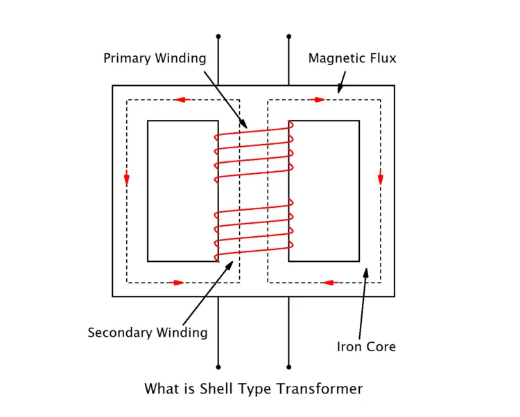
All these names point to the same basic idea—a transformer with windings safely wrapped inside a sturdy core for better performance and durability. Think of it as a protective “shell” of metal wrapped around the delicate copper coils. The windings are typically placed on the central limb of the core, while the two outer limbs serve as the return path for the magnetic flux.
This distinct arrangement stands in contrast to core-type transformers, where the windings surround the core. The shell design is specifically favored when the primary goal is to maintain high structural integrity and minimize leakage reactance, ensuring that the maximum amount of power is transferred efficiently from the primary to the secondary side.
Construction of Shell Type Transformer
The exceptional performance of a shell-type transformer stems directly from its unique, robust construction. Unlike core transformer types, in which the windings surround the core, the shell design reverses this arrangement.
Here, the core envelops the windings, providing both mechanical protection and a highly efficient magnetic circuit. Let’s explore the specific components and assembly process that define this powerful design.
Core Design and Assembly
The foundation of a sandwich transformer is its distinctive magnetic core structure. This core is engineered to provide a low-reluctance path for the magnetic flux, ensuring maximum energy transfer.
Laminated Core Structure
- The shell core transformer is not a solid block of iron. Instead, it is built from thin, high-grade silicon steel laminations, typically 0.35-0.5 mm thick.
- Each lamination is coated with a thin layer of insulating varnish or oxide before being stacked together.
- This laminated-core construction is crucial for minimizing eddy-current losses, unwanted electrical currents induced in the core that generate heat and reduce efficiency. Breaking the conductive path significantly improves the transformer’s overall performance.
- Shell transformer core is made U and T shape or Tand E shape laminations. The complete core design is created by combining the shapes of these two laminations.
Double Magnetic Path
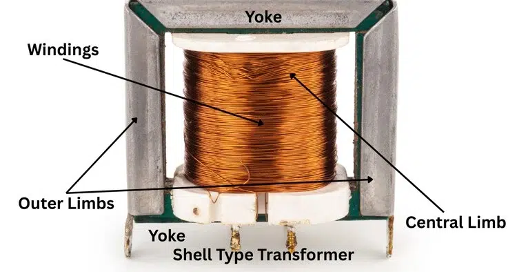
A key feature of the shell transformer core design is its multi-limb structure, which creates a double or parallel magnetic circuit. The core consists of a central limb and two outer limbs (or side yokes). The entire set of windings is placed on the central limb.
When the transformer is energized by supplying an AC electric current to the primary winding. the magnetic flux generated in the central limb splits into two halves. Each half travels through one of the outer limbs to complete its circuit. This design ensures that the cross-sectional area of the central limb is double that of each outer limb, as it must carry the total flux. This efficient magnetic flux path is fundamental to the shell transformer’s low magnetic leakage.
The Winding Arrangement
The defining characteristic of a Multi limbs transformer is its winding placement. This method involves interleaving the high-voltage (HV) and low-voltage (LV) coils in an alternating pattern.
Interleaving Coils
- Instead of having one large LV coil and one large HV coil, both are subdivided into smaller disc-shaped coils. These discs are then stacked on the central limb in a “sandwich” formation: LV, HV, LV, HV, and so on.
- This arrangement is not arbitrary; it is a deliberate engineering choice to minimize leakage reactance. Placing the HV and LV coils in proximity ensures a very tight magnetic coupling.
- The tight coupling significantly improves voltage regulation, meaning the output voltage remains more stable under varying loads.
Winding Insulation and Support
- Proper winding insulation is critical to prevent electrical breakdowns between the coils and between the coils and the core.
- Insulating materials like paper, pressboard, and mica are placed between the winding layers and sections.
- Furthermore, the coils are held rigidly in place with braces and supports. This mechanical bracing is a major advantage of the shell-type design, as the core itself provides excellent support against the immense electromagnetic forces generated during a short circuit.
Transformer Oil
- For oil-cooled transformers, the tank is filled with insulating transformer oil.
- The oil serves two primary purposes: it provides additional electrical insulation. It acts as a coolant, transferring heat from the core and windings to the tank walls, which then dissipate it into the atmosphere.
Bushing
Bushings are mounted on the tank to provide insulated terminals for connecting the transformer to the external electrical circuit.
Final Transformer Assembly
Once the core is stacked and the windings are carefully placed and insulated on the central limb, the final transformer assembly takes place. The top yoke of the laminated core is put into position, completing the magnetic circuit. The entire assembly of the core and windings is then securely clamped and placed inside a steel tank.
Working Principle of Shell Type Transformer
Let’s learn step by step how a sandwich transformer works, from creating the magnetic field to the final output voltage.
- Creating the Magnetic Field: As the AC flows through the primary coils, it generates a changing magnetic field, or magnetic flux, in the transformer’s central core limb. The magnitude and direction of this flux change continuously, mirroring the AC supply.
- Flux Linkage: This alternating magnetic flux travels through the low-reluctance path provided by the laminated iron core. As it does, it “links” with both the primary and secondary windings that are stacked together on the central limb.
- Inducing Voltage: According to Faraday’s Law of Electromagnetic Induction, this changing flux induces a voltage (an electromotive force or EMF) in the secondary winding. The magnitude of this induced voltage is directly proportional to the ratio of turns between the secondary and primary coils. If the secondary winding has more turns than the primary, the voltage is stepped up. If it has fewer turns, the voltage is stepped down.
Learn more about:- Working principle of transformer
Advantages of a Shell Type Transformer
The unique design of the Shell transformer offers a range of specific benefits, making it the ideal choice for certain electrical applications.
- Mechanical Strength and Durability: One of the most significant advantages is its exceptional mechanical robustness. In a sandwich transformer, the windings are securely supported by the central core limb and braced by the surrounding outer limbs. This rigid structure provides excellent protection against the immense electromagnetic forces generated during short-circuit conditions.
- Reduced Leakage Reactance: The high-voltage (HV) and low-voltage (LV) coils are subdivided and interleaved in an alternating pattern. This arrangement creates a very tight magnetic coupling between the primary and secondary windings, which significantly minimises leakage flux. The resulting low leakage reactance improves voltage regulation, ensuring a more stable output voltage even under fluctuating load conditions.
- Excellent Cooling: While the windings are enclosed, the core itself has a large surface area exposed to the cooling medium (typically oil or air). This design enables more efficient heat dissipation from the core, where a significant portion of transformer losses (core losses) occur. Better cooling helps prevent overheating, increases the transformer’s lifespan, and allows the multi-limb transformer to operate efficiently for extended periods.
- High-Current Applications: For low-voltage, high-current applications, the shell type design can often be more compact than a core-type equivalent. The enclosed core transformer structure provides shorter magnetic paths, reducing the amount of core material required for a given power rating. This makes it a practical choice for equipment where space is a consideration, such as in welding machines or electric furnaces.
- High Efficiency: The combination of low leakage reactance and a highly contained magnetic flux path contributes to the high efficiency of a shell transformer. This efficiency is a key reason the sandwich-type transformer is favoured in applications where minimising energy loss is a priority.
- Protection for Windings: The fundamental design of an enclosed core transformer means the delicate windings are naturally protected from external physical damage.
Disadvantages of Shell Type Transformer
Here are the primary drawbacks associated with shell transformer design.
- Complex Manufacturing : One of the most significant barriers to adopting a shell-type transformer is the complexity of its fabrication. Unlike core-type transformers, which have simpler cylindrical windings, Enclosed core transformers require more time and specialised equipment to assemble. This complexity often translates into higher manufacturing costs and longer production lead times.
- Maintenance and Repair: The very feature that provides mechanical protection—the enclosed core—also makes maintenance a challenge. In an enclosed core transformer, the windings are surrounded by the magnetic core. If a fault occurs in the inner coils, accessing them for repair is extremely difficult. This labour-intensive process increases downtime and repair costs, making field repairs less practical than for other transformer types.
- Reduced Cooling Efficiency: The core of a multi-limb transformer has a large surface area for cooling, but the windings themselves are buried deep within the structure. Because the coils are surrounded by an iron core, natural air circulation around the windings is reduced. Therefore, sandwich transformers often require more advanced cooling systems, thereby increasing the overall system’s cost and complexity.
- Higher Iron Loss: Shell designs typically have more iron core material than core-type transformers of the same rating. This results in greater hysteresis and eddy current losses. These “iron losses” occur continuously as long as the transformer is energised, regardless of load.
- Heavier and Bulkier Construction: Due to the massive core structure required to enclose the windings, these transformers tend to be heavier and bulkier than their core-type counterparts.
Application of Shell Type of Transformer
Its ability to handle high currents while maintaining excellent voltage stability means it is not a one-size-fits-all solution. Instead, it excels in specific, demanding scenarios where other transformer types might fall short. Here are some of the main applications where shell core transformers are the preferred choice.
Use High-Current, Low-Voltage
One of the most common applications is in equipment that requires a very high current output at a relatively low voltage.
- Arc Welding: A Sandwich Transformer is used for Electric arc welding machines that require a stable, high-current supply to create and maintain an arc. A multi limbs transformer can deliver this power reliably without a significant voltage drop.
- Electric Furnaces: Induction furnaces and arc furnaces used in metallurgy for melting metals rely on immense currents. The robust construction of a Shell core power transformer is ideal for handling the demanding, cyclical loads of these industrial powerhouses.
Use Electronic Equipment
Sandwich transformers used in modern power electronics and converter circuits benefit greatly from their stable voltage output.
- Rectifier Circuits: They are often used in power supplies for converting AC to DC, where a stable voltage is essential for the performance of the connected electronic components.
- Inverter and Converter Systems: The enclosed-core transformer is used in uninterruptible power supplies (UPSs) and variable-frequency drives (VFDs), where reliable power conversion is key.
Use Industrial Control
The compact and durable nature of the multi-limb transformer makes it suitable for integration into control panels and heavy machinery. Its inherent mechanical strength allows it to withstand vibrations and mechanical stresses common in industrial environments.
- Control Transformers: They serve as control transformers, stepping down voltage to power relays, solenoids, and control circuits within automated systems.
- Heavy Machinery: The physical protection provided by the enclosed-core transformer design makes it a reliable choice for electrical equipment installed directly on or near heavy manufacturing machinery.
Use Testing and Laboratory Equipment
The excellent voltage stability and low reactance of a Shell form transformer make it ideal for powering sensitive test equipment.
- High-Current Injection Testing: It is used in setups for testing circuit breakers and other protective devices that require a precise, high-current source.
- Calibration Labs: Stable output ensures calibration standards are met during testing and certification of other electrical instruments.
Conclusion
As we’ve explored, the key strengths of a Shell type transformer lie in its exceptional mechanical robustness, superior voltage regulation due to its low leakage reactance, and its suitability for high-current, low-voltage applications. While it may be more complex to manufacture and repair, its advantages make it the indispensable choice for powering electric furnaces, arc welders, and sensitive industrial control systems.
FAQ
What is the Main Advantage of Using a Shell Type Transformer?
The biggest advantage is its mechanical strength. Because the core surrounds the windings, it acts as a rigid brace, preventing the coils from moving or deforming during operation. This makes the shell transformer exceptionally durable and capable of withstanding the massive electromagnetic forces generated during a short circuit.
Does the Shell Design Improve Voltage Regulation?
Yes, it does. The “sandwich” winding technique brings the primary and secondary coils very close together. This tight coupling drastically reduces leakage reactance (magnetic flux that doesn’t link both coils). Lower leakage means the output voltage remains steady even when the transformer load fluctuates.
Is a Shell-Type Transformer Suitable for Power Distribution Networks?
While shell core power transformers are used in power distribution, especially where high current and strong voltage regulation are required, their complex design and cooling requirements often make them less suitable than core-type transformers for large, conventional distribution networks.
I am an electrical engineer and also a blogger. I write informative blog posts on topics related to electrical and electronics engineering. If you are interested in these topics, you are welcome to my site to read these articles.