What is Core Type Transformer
Transformer designs are categorized into various types, primarily based on their application and performance requirements. Among these, the core type transformer stands out as a widely used design due to its superior performance and mechanical strength. This design is highly efficient in power transmission and is equally suitable for domestic electrical appliances. The core-type structure ensures minimal energy loss and enhanced durability, making it a preferred choice in industries and households alike. Its robust construction not only supports high power handling but also ensures reliability under varying operational conditions. By optimizing energy transfer and reducing maintenance needs, core transformers play a crucial role in modern electrical systems. In this article, you will learn everything you need to know about core-type transformers.
What is Meant by Core Type Transformer
A core transformer is a specific design of transformer where the windings (primary and secondary) are wound around a laminated magnetic core. The core is typically rectangular in shape and made of thin, insulated sheets of high-grade silicon steel to minimize energy losses due to eddy currents. In this design, the core forms the central structure, and the windings are placed around it, either on one or both limbs of the core.
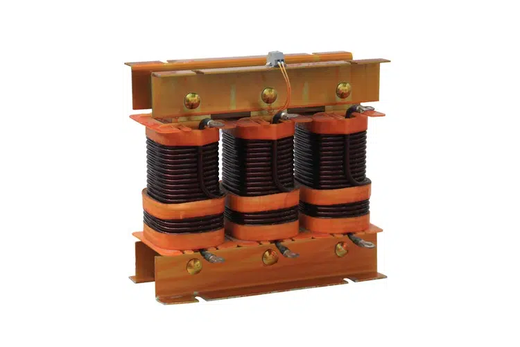
The core-type transformer is known for its robust construction and efficient energy transfer. It is widely used in power transmission systems, industrial applications, and even domestic appliances due to its ability to handle high power loads with minimal energy loss. Its design ensures better mechanical strength, reduced noise levels, and improved cooling efficiency.
This type of transformer is ideal for applications requiring high reliability and performance, making it a preferred choice in modern electrical systems.
Core Type Transformer Construction
In the architecture of modern electrical systems, the core transformer stands out for its durability and efficiency. Its design focuses on maximizing magnetic coupling while minimizing energy loss.
To understand how this device works, we need to understand its basic structure and components. Let us step through the construction of a transformer core type in detail.
Transformer Core
Core Materials
The heart of any transformer is its magnetic core. In a core transformer, manufacturers typically use high-grade cold-rolled grain-oriented (CRGO) silicon steel. This material is chosen for its high magnetic permeability, which allows magnetic flux to flow easily.
The core is not a solid block of steel. Instead, it is built from stacks of thin steel sheets called laminations. These laminations are insulated from one another by a thin layer of varnish. This layered approach is critical. If the core were solid, it would generate significant heat due to circulating currents known as “eddy currents.” Laminating the core breaks these currents’ path, drastically reducing energy loss and keeping the transformer cool.
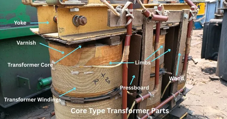
Regarding shape, the core usually forms a rectangular or square frame. This structure provides a continuous path for the magnetic flux and serves as a sturdy skeleton for the windings.
Core Design
The transformer’s structural integrity depends on its core design. The vertical sections of the core frame are called limbs (or legs), and the horizontal sections connecting them are called yokes.
In a transformer core type, the windings surround the limbs. Since the windings encircle the core, this design offers excellent mechanical strength. It can withstand the high mechanical forces generated during short circuits or heavy electrical faults.
This robustness makes the core-type design particularly suitable for high-voltage and high-power applications where stability is non-negotiable.
Transformer Windings
The windings are the conductors that carry the electrical current. In core transformers, we use two main sets of windings: the primary (input) and the secondary (output).
Ideally, these windings are made from high-conductivity copper. Copper minimizes resistance, reducing energy waste as heat. However, in cost-sensitive applications, aluminum is sometimes used as a lighter, albeit slightly less conductive, alternative.
The arrangement of these windings is unique in core-type designs. We arrange them concentrically (one inside the other) around the core limbs. Typically, the Low Voltage (LV) winding is placed closer to the core, while the High Voltage (HV) winding surrounds it.
This placement simplifies the insulation requirements, as the core is at ground potential. Proper insulation between these layers is vital to prevent electrical faults and ensure safe operation.
Insulation System
Insulation is the unsung hero of transformer construction. Without it, the device would short-circuit immediately. In a transformer core type, the insulation system consists of various materials, such as oil-impregnated paper, pressboard, wood, and varnish.
You will find insulation layers in several critical areas:
- Between the core and the windings: To prevent current from flowing into the steel frame.
- Between the primary and secondary windings: To separate the input and output circuits electrically.
- Between individual turns of wire: To ensure current flows through the entire length of the coil.
These layers act as barriers, preventing short circuits and ensuring the electrical energy stays in the conductor where it belongs.
Cooling System
Even the most efficient transformers generate heat during operation. If this heat is not managed, it can damage the insulation and reduce the transformer’s lifespan. Therefore, an effective cooling system is essential.
For smaller transformers, natural air cooling is often sufficient. The heat radiates from the surface into the surrounding air. However, larger transformers require more aggressive cooling methods. We often submerge the core and windings in a tank filled with mineral oil. This oil serves a dual purpose: it acts as a coolant to dissipate heat and provides additional electrical insulation.
By maintaining an optimal operating temperature, the cooling system directly impacts the transformer’s efficiency. A cooler transformer runs more smoothly and lasts longer.
Magnetic Flux Path
The primary function of the core is to provide a low-reluctance path for magnetic flux. When you energize the primary winding, it creates a magnetic field. This flux travels through the limbs and yoke to reach the secondary winding, inducing voltage.
In a core-type transformer, the magnetic circuit is simple: the flux flows through a single path in single-phase units (or multiple specific paths in three-phase units). The design aims to keep this path as short and tight as possible. By wrapping the windings closely around the core limbs, engineers minimize “leakage flux”—magnetic energy that escapes into the air instead of linking the two coils. Reducing leakage flux improves voltage regulation and overall performance.
By optimizing these six construction elements, the core transformer delivers the reliability and power handling capability required for modern electrical grids and industrial machinery.
Core Type Transformer Working Principle
Step-by-Step Working Principle of Core Type Transformer:
- AC Supply to Primary Winding: When an alternating current (AC) is applied to the primary winding wrapped around a laminated silicon steel core, it creates a varying magnetic field.
- Magnetic Flux in the Core: This changing magnetic field generates magnetic flux that follows a closed magnetic path through the core.
- Mutual Induction: The alternating magnetic flux passes through both the primary and secondary windings, which are placed concentrically on the core limbs.
- Induced EMF in Secondary: According to Faraday’s Law, this fluctuating flux induces a voltage (EMF) in the secondary winding.
- Energy Transfer to Load: When a load is connected to the secondary, current flows, and electrical energy is transferred from primary to secondary purely through magnetic coupling—no direct electrical connection.
- Voltage Transformation: The voltage output depends on the ratio of turns between the windings. More turns in the secondary winding provide a step-up transformer; fewer turns give a step-down transformer. The frequency stays the same as the input.
Types of Core-Type Transformers
When we talk about core transformers, it is easy to assume they are all built the same way. However, this category includes several distinct variations designed for specific voltage levels, applications, and power requirements.
Core Type Single Phase Transformer
- Structure: It features a simple rectangular core frame with two vertical limbs and two horizontal yokes. The windings (both primary and secondary) are placed on the two side limbs. To minimize leakage flux, half of the primary winding and half of the secondary winding are often placed on each limb in a concentric arrangement.
- Applications: These are typically found in small-scale applications, such as domestic appliances, small power supplies, and localized voltage step-down tasks.
- Advantages: Single phase transformer are simpler to manufacture, easier to repair, and cost-effective for low-power requirements.
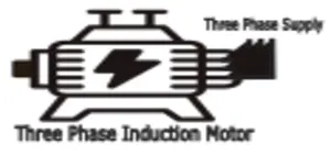
3 Phase Core Type Transformer
In industrial and large-scale power systems, single-phase units are often insufficient. This is where the three-phase core-type transformer comes in.
- Design: Instead of two limbs, this core has three vertical limbs—one for each phase (R, Y, B). Yokes connect the top and bottom to complete the magnetic circuit. The primary and secondary windings of each phase are wound around one of the three limbs.
- Role: These are the workhorses of the electrical grid. They are used extensively in power generation plants, transmission substations, and heavy industrial factories.
- Benefits: A single three-phase unit occupies less space and is cheaper than using a bank of three separate single-phase transformers. The magnetic circuit is slightly unbalanced due to the central limb, but the design is highly efficient for handling large loads.
Core Type Transformer Advantages and Disadvantages
When selecting a transformer design for a specific electrical application, understanding the pros and cons is crucial. The transformer core type is a popular choice in power transmission and industrial settings, but, like any engineering solution, it has its own strengths and weaknesses.
Advantages
- High Mechanical Strength: The most significant advantage of this design is its structural integrity. Since the windings surround the core limbs, the overall structure is cylindrical and highly resistant to mechanical stresses. This makes the transformer capable of withstanding the severe forces generated during short circuits.
- Efficient Cooling: In a core-type design, a significant portion of the windings is exposed to the surrounding air or oil. This exposure improves heat dissipation. Because the windings are not enclosed by the core itself (as they are in shell-type transformers), it is much easier to implement effective cooling systems, ensuring the device runs at optimal temperatures.
- Ease of Maintenance: If a fault occurs, accessing the windings for repair or inspection is relatively straightforward. Since the windings are placed on the outside of the core limbs, technicians can easily dismantle and reassemble the coil structure without disassembling the entire magnetic core.
- Ease of Maintenance: If a fault occurs, accessing the windings for repair or inspection is relatively straightforward. Since the windings are placed on the outside of the core limbs, technicians can easily dismantle and reassemble the coil structure without disassembling the entire magnetic core.
- Ease of Maintenance: If a fault occurs, accessing the windings for repair or inspection is relatively straightforward. Since the windings are placed on the outside of the core limbs, technicians can easily dismantle and reassemble the coil structure without disassembling the entire magnetic core.
Disadvantages
- Higher Leakage Flux: In this design, the magnetic flux has a longer path to travel through the limbs and yoke. As a result, there is a greater potential for magnetic flux leakage in shell-type transformers. While this can be managed with good design, it inherently affects voltage regulation.
- Larger Footprint: For the same kVA rating, a core-type transformer often requires more space than a shell-type equivalent. The physical arrangement of the limbs and yokes can make the overall unit bulkier, a disadvantage in applications with severely limited space.
- Higher Noise Levels: Transformers vibrate during operation due to magnetostriction (magnetic forces acting on the core steel). Core transformers tend to generate more audible noise, or “hum,” than shell-type designs, which brace the core more tightly.
- Requires More Copper: Because the windings surround the core, the mean turn length in the coil is often longer. This means a transformer core type may require more copper wire for the windings, potentially increasing material costs.
- Sensitivity to External Magnetic Fields: Because the windings are exposed on the outside, they are slightly more susceptible to interference from external magnetic fields than designs in which the core encloses the windings.
Core Type Transformer Applications
The core-type transformer is a foundational component in modern electrical engineering, known for its robust construction and high efficiency.
Power Transmission and Distribution
The primary application of core transformers is in high-voltage power transmission systems. Power plants generate electricity at a relatively low voltage, which must be “stepped up” to extremely high voltages for efficient long-distance transport. Core transformers are ideal for this role due to their excellent mechanical strength, which enables them to withstand the immense electrical and physical stresses involved.
Their superior insulation and cooling capabilities make them reliable for continuous operation in substations. Similarly, at the other end of the line, they are used as step-down transformers to reduce the voltage for distribution to cities and industrial areas.
Industrial Applications
Factories and industrial plants rely on heavy machinery that consumes large amounts of power. Transformers core type are frequently used to supply the specific voltage required by motors, furnaces, welding equipment, and other industrial loads.
Their durable construction ensures they can withstand the demanding environment of a manufacturing facility, including vibrations and fluctuating power demands. The ease of maintenance is another significant benefit in industrial settings, as it minimizes downtime during repairs.
Domestic and Commercial Applications
While large core transformers power our cities, smaller versions are present in many of the devices we use daily. They are found in a variety of household and commercial electrical appliances that require a stable, reliable power supply.
For example, they can be part of the power supply units for computers, audio systems, and other electronics. Their efficiency ensures minimal heat waste, making them a safe and effective choice for consumer goods.
Renewable Energy Systems
The global shift towards renewable energy has opened up new applications for core transformers. In wind and solar power generation, electricity is often produced at variable voltages. Transformers are essential for stabilizing this power and stepping it up for connection to the main electrical grid.
The reliability and high efficiency of core-type transformers make them ideal for integrating clean energy sources into our existing power infrastructure, ensuring that energy from wind turbines and solar panels is delivered with minimal loss.
Specialized Applications
- Medical Equipment: Devices such as MRI machines and X-ray systems require precise, stable high-voltage power supplies. Core transformers provide the reliability needed to ensure these critical medical instruments function safely and accurately.
- Research Laboratories: Scientific research often involves experiments that demand highly controlled electrical conditions. Custom-built transformer core type are used in labs to power sensitive equipment and create specific electromagnetic fields for testing and analysis.
- Testing Facilities: They are also used as testing transformers to assess the insulation and durability of other high-voltage electrical components.
Conclusion
In conclusion, core-type transformers play a vital role in the backbone of modern electrical infrastructure, offering unmatched versatility and adaptability across a wide spectrum of applications. From compact single-phase units serving household devices to robust three-phase transformers powering industrial complexes and large-scale distribution networks, their varied designs ensure reliable, efficient, and safe energy management at every level.
FAQ
Why Core Type Transformer is Used for High Voltage
Core-type transformers are used for high voltage applications due to their robust mechanical strength, efficient cooling, and superior insulation. Their design minimizes energy losses and ensures reliable performance under the high electrical and physical stresses of high-voltage systems.
How Many Limbs in Core Type Transformer
A core-type transformer typically has two limbs (vertical sections of the core). These limbs support the windings and form part of the magnetic circuit, ensuring efficient energy transfer.
How Many Yoke in Core Type Transformer
A core-type transformer has two yokes, which are the horizontal sections of the core. These yokes connect the limbs at the top and bottom, completing the magnetic circuit and ensuring efficient flux flow.
How Many Magnetic Path in Core Type Transformer
A core-type transformer has a single magnetic path. The magnetic flux flows through the core, travelling up one limb, across the yoke, down the other limb, and back, forming a continuous closed loop for efficient energy transfer.
I am an electrical engineer and also a blogger. I write informative blog posts on topics related to electrical and electronics engineering. If you are interested in these topics, you are welcome to my site to read these articles.