Armature reaction in DC machine(Generator and Motor)
The performance and efficiency of DC machines depend primarily on the interaction of their magnetic fields. One of the key principles governing this interaction is armature flux reaction. Understanding this subject is crucial, as it directly affects the machine’s functionality, stability, and lifespan. In a DC machine, armature field reaction refers to the interaction between the magnetic field produced by the armature current and the main field flux. This interaction is not always beneficial. These effects can lead to reduced machine performance, sparking at the brushes, and decreased overall efficiency. Therefore, a thorough understanding of armature reaction is not only an academic requirement but also essential for the design, operation, and maintenance of the machine.
In this article, we will study in detail the effects of armature reaction, methods to reduce it, and its role in the operation of a DC machine.
What is Armature Reaction
In any DC machine, there is an interaction between two main magnetic fields that enables the machine’s operation. The first is the main magnetic field, which is generated by the field winding on the stator poles. The second is the magnetic field generated by the current flowing through the electrical conductors (armature), the rotating part of the machine. When the machine is connected to a load, current flows through the armature conductors, generating its own magnetic flux. The effect of this magnetic flux generated by the armature on the main magnetic field is called armature magnetic flux reaction.
Armature Reaction in DC Generator
In a DC generator, the interaction of the two magnetic fields significantly contributes to voltage regulation and overall efficiency. When the generator operates without a load, only the magnetic flux produced by the main field poles is present. This flux is uniform and balanced. However, as soon as the generator is connected to an external load, current flows through the armature conductors. This armature current creates its own magnetic field, which interferes with the main flux. This specific effect of magnetic distortion in the generator is called armature field reaction.
Armature Reaction in DC Motor
In a DC motor, the interaction between the two magnetic fields is crucial for torque production and speed control. When the motor is unloaded, only the magnetic flux created by the main field poles is present, and it is perfectly symmetrical. However, as soon as the motor is started and a mechanical load is applied, current flows through its armature conductors. This current creates its own magnetic field, which interacts with the main flux. This magnetic effect occurring in the motor is called armature reaction.
Principle of Armature Reaction
The fundamental principle of operation of a DC machine depends on the presence of two main magnetic fields. The first is produced by the field poles mounted on the stator; it is called the main flux. This field is present even when the machine is running without any load. The second magnetic field is generated when a load is applied to the machine, and current begins to flow through the armature conductors. Faraday’s law states that whenever electric current flows through a conductor, a magnetic field is generated around it. This magnetic field, created by the armature conductors, is called the armature flux.
The principle of magnetic flux distortion is based on the interaction between these two magnetic fields—the main flux and the armature flux. When the machine is running without a load, only the main flux is present, uniformly distributed in the air gap. However, as soon as current flows through the armature due to the load, an armature flux is also generated. This armature flux interferes with the main flux, thereby altering its path.
Why Armature Reaction occur
This magnetic interference occurs because both magnetic fields attempt to occupy the same space (the air gap). The direction of the armature flux is perpendicular to the direction of the main flux. Due to this interaction, the straight and symmetrical path of the main flux is distorted. At one end of the poles, the armature flux weakens the main flux, while at the other end, it strengthens it. This distortion and effect on the main magnetic field is called armature reaction. In short, this phenomenon is a natural consequence of the magnetic flux produced by the armature current acting on the main magnetic field under load conditions.
Effect of Armature Reaction in DC Machine
Before understanding the effects of these reactions on a DC machine, it is essential to learn about two critical axes: the GNA and the MNA. Without understanding these two, it is difficult to comprehend the changes in the magnetic field fully.
MNA and GNA in DC Machine
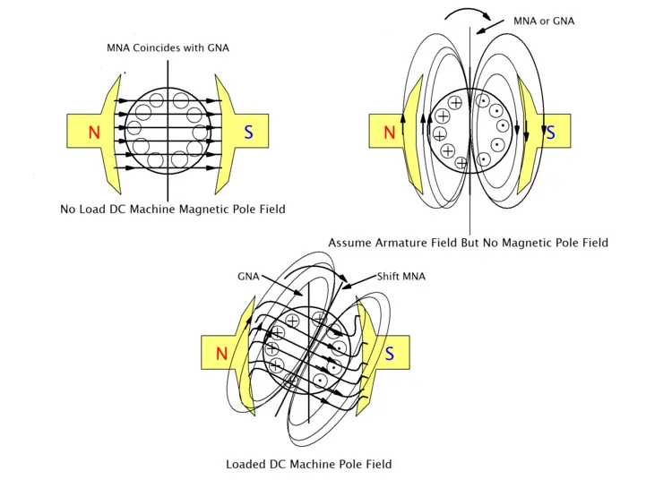
- Geometric Neutral Axis(GNA): This is the imaginary line or axis that runs exactly midway between the main field poles of the machine. It depends on the machine’s design and geometry, and remains constant whether the machine is running, stopped, or under load. It is located at a 90-degree angle to the centre of the poles.
- Magnetic Neutral Axis(MNA): This is the imaginary line where the induced voltage (EMF) in the armature conductors is zero. There is no magnetic flux along this axis. In an ideal situation, when the machine is unloaded, the MNA (Magnetic Neutral Axis) and GNA (Geometric Neutral Axis) coincide. The brushes are always positioned on the MNA to prevent sparking.
Effect of Armature Reaction
When a load is applied to a DC machine, current flows through the armature, and this is where the effect of armature reaction begins. It primarily has two significant effects:
1. Field Distortion
As the armature flux interacts with the main field flux, the resulting magnetic field shifts slightly from its original position. Since the MNA (Magnetic Neutral Axis) is always perpendicular to the resultant flux, when the flux shifts, the MNA also moves from its original position.
- In the generator case: the MNA shifts forward in the direction of rotation.
- In the motor case: The MNA shifts in the opposite direction of rotation.
Due to this field distortion, the brushes no longer remain at the new MNA position (because they are fixed at the GNA), which leads to sparking during commutation.
2. Flux Weakening
Another significant consequence of the armature field effect is the weakening of the main magnetic field. When the armature flux strengthens the main flux on one side and weakens it on the other, the increase in total flux due to iron saturation is less than the decrease in the main flux. This results in a reduction of the machine’s net flux. In a generator, this reduces the generated voltage; in a motor, it reduces torque and makes the speed unstable.
Types of Armature Reaction in DC Machine
The effect of the armature’s magnetic field on the main field is not uniform. Based on its orientation relative to the main field flux, the effect of armature reaction is divided into two main parts: the cross-magnetising effect and the demagnetising effect. Let’s analyse and understand these two types of impact in more detail.
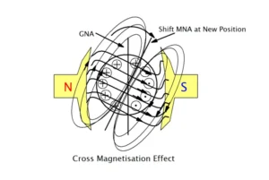
1. Cross-Magnetizing Effect
This is the central part of flux displacement. This effect occurs because the magnetic field of the armature is perpendicular (at 90 degrees) to the main flux. Due to this vertical orientation, the armature flux “crosses” the path of the main flux and distorts it.
Features and effects:
- Distortion of the main flux: This effect does not directly oppose or assist the main field, but instead pushes and distorts it. This leads to an increase in flux density at one pole tip and a decrease at the other.
- Shift in the Magnetic Neutral Axis (MNA): The most significant consequence of the cross-magnetising effect is the shifting of the magnetic neutral axis (MNA). The MNA is the plane where the induced voltage (EMF) in the armature conductors is zero. This effect displaces this plane from its original position along the geometric neutral axis (GNA).
- Sparking at the brushes: Since the brushes are typically fixed at the GNA (Geometric Neutral Axis), when the MNA (Magnetic Neutral Axis) shifts, the brushes short-circuit conductors that still carry current. This causes sparking between the brushes and the commutator, which can shorten the lifespan of both components.
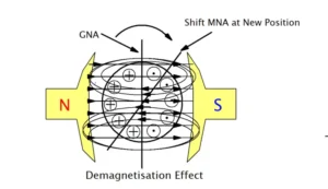
2. Demagnetizing Effect
The demagnetising effect is the secondary component of armature reaction that directly weakens the main flux. While cross-magnetising distorts the field, demagnetising reduces its overall strength. This occurs because a portion of the armature flux directly opposes the main flux.
Features and effects:
- Reduction in total flux: The demagnetising component acts against the main flux, resulting in a reduction in the total flux per pole. While the cross-magnetising effect strengthens one pole tip and weakens the other, the increase does not fully compensate for the decrease due to magnetic saturation in the iron, and the net total flux is reduced.
- Impact on generator performance: In a DC generator, the generated EMF is proportional to the flux. Due to the decrease in flux, the terminal voltage decreases as the load increases.
- Impact on motor performance: In a DC motor, the speed is inversely proportional to the magnetic flux. When the flux weakens, the motor speed can increase with increasing load, potentially affecting its stability. Additionally, torque decreases because it is directly proportional to flux.
Mathemetical Analysis of Armature Reaction
To understand the effects of armature reaction, it is necessary to analyse the magnetomotive force (MMF) involved. The impact of the armature field can be divided into two main components: the cross-magnetising effect and the demagnetising effect. These effects are measured in ampere-turns (AT), a unit that represents the strength of the magnetic field.
Let’s assume the main parameters:
- Z = Total number of armature conductors
- P = Number of poles in a DC machine
- I = The current flowing through each armature conductor
- A = Number of parallel paths in the armature winding (A = 2 for wave winding, A = P for lap winding)
- \(I_a\) = Total armature current
- \(θ_m\) = Angle of mechanical shift of the brush from GNA
The current flowing through each conductor is
= \(\frac{I_a}{A}\)
.
Armature ampere-turns per pole (\(\frac{AT_a}{\text{pole}}\)):
The MMF produced by the armature is calculated from the total number of conductors and the current flowing through them. The total number of turns in the armature is \(Z/2\), and these turns are distributed among P poles; therefore, the armature turns per pole are:
= \(\frac{Z}{2P}\)
Therefore, total armature ampere-turns per pole =
\(\frac{AT_a}{\text{pole}} = \left( \frac{Z}{2P} \right) \cdot I = \frac{Z \cdot I_a}{2 \cdot P \cdot A}\)
This entire armature MMF is directed along the brush axis. However, due to the brush shift and the main field orientation, this MMF splits into two components.
Demagnetizing ampere-turns per pole (\(\frac{AT_d} {\text{pole}}\))
The demagnetising component of armature reaction opposes and weakens the main field flux. This effect is caused by the armature conductors that come within the region of the pole shoe after the magnetic neutral axis (MNA) shifts. The angle covered by these conductors is twice the angle of brush shift \((2\theta_m)\).
Number of armature conductors responsible for the demagnetising effect:
Conductors within the \(2\theta_m\) angle
Number of conductors in angle \(2\theta_m = \left( \frac{\text{Total conductors}}{360^\circ} \right) \cdot 2\theta_m\)
= \(\left( \frac{Z}{360^\circ} \right) \cdot 2\theta_m\)
Since these conductors form turns,
Demagnetizing turns per pole = \(\frac{1}{2} \cdot \left( \frac{Z \cdot 2\theta_m}{360^\circ} \right) = \frac{Z \cdot \theta_m}{360^\circ}\)
Now, demagnetising ampere-turns per pole:
\(\frac{AT_d}{\text{pole}} = \left( \frac{Z \cdot \theta_m}{360^\circ} \right) \cdot I\)
Substituting \(I = \frac{I_a}{A}\) here:
\(\frac{AT_d}{\text{pole}} = \frac{Z \cdot I_a \cdot \theta_m}{360^\circ \cdot A}\)
Cross-magnetizing ampere-turns per pole (\(\frac{AT_c} {\text{pole}}\))
The cross-magnetising component acts perpendicular to the main field flux, distorting the field. This is due to the remaining conductors that do not participate in demagnetisation.
Cross-magnetising ampere-turns:
Total armature ampere-turns – Demagnetising ampere-turns
\(\frac{AT_c}{\text{pole}} = \frac{AT_a}{\text{pole}} – \frac{AT_d}{\text{pole}}\)
\(\frac{AT_c}{\text{pole}} = \left( \frac{Z \cdot I_a}{2 \cdot P \cdot A} \right) – \left( \frac{Z \cdot I_a \cdot \theta_m}{360^\circ \cdot A} \right)\)
How to Reduce Armature reaction in DC Machine
For efficient and reliable operation of a DC machine, controlling the magnetic interference generated by the armature is crucial. If this effect is not mitigated, it severely impacts the machine’s performance, leading to sparking at the commutator, voltage or speed instability, and reduced overall efficiency. Three primary methods are used to minimise these detrimental effects of armature field effect:
1. By Brush Shifting
This is the simplest, but oldest, method for reducing armature reaction. As we know, due to field distortion, the magnetic neutral axis (MNA) shifts from its original position (GNA). Since the brushes must always be positioned on the MNA for spark-free commutation, this is achieved by physically turning the brushes to the new MNA position.
- In a generator, the brushes are shifted forward in the direction of rotation.
- In a motor, the brushes are shifted in the direction opposite to rotation.
Although this method is best suited for small motors, it has a significant drawback. When the load changes, the armature current changes, shifting the magnetic neutral axis (MNA). This means the brushes would have to be repositioned each time the load changes, which is not practically feasible.
2. Interpoles or Commutating Poles
This is the most effective way to eliminate the cross-magnetising effect of armature reaction, which is the primary cause of commutation problems. Interpoles are small poles placed between the main field poles.
Interpoles create a magnetic field that precisely neutralises the effect of the armature flux in the commutating zone, right where its influence is strongest. Since the interpoles are connected in series with the armature, when the load increases and the armature flux increases, the interpole flux also increases proportionally, effectively cancelling it out. This ensures spark-free commutation and keeps the brushes fixed at the geometric neutral axis (GNA).
2. Compensating Winding
Interpoles only correct field distortion in the commutating zone, but the distortion of the main flux under the pole shoes remains. To solve this problem, compensating windings are used, especially in large and high-capacity machines.
The compensating winding current direction is precisely opposite to the direction of the armature conductors’ current flowing located under the pole shoes. This creates a magnetic field that wholly and directly neutralises the armature flux. This not only eliminates the cross-magnetising effect but also significantly reduces the demagnetising effect.
Conclusion
Understanding armature reaction in DC machines is crucial for engineers and technicians to optimise electrical performance and lifespan. The inherent magnetic interaction between the armature flux and the main flux can cause sparking, voltage fluctuations, and speed instability. While these effects are natural during the machine’s operation under load, they can be effectively mitigated through appropriate design measures, such as interpoles, compensating windings, and proper brush settings. Ultimately, mastering armature field effect management is key to transforming a basic electrical machine into an efficient and reliable industrial device.
FAQ
What is the Effect of Armature Reaction in DC Generator
In a DC generator, armature flux disturbance weakens the main flux, distorts the magnetic field, and shifts the Magnetic Neutral Axis (MNA). This causes voltage drops, sparking at the brushes, and poor voltage regulation, which affect overall performance and efficiency.
What is the Effect of Armature Reaction in DC Motor
In a DC motor, flux distorts the main magnetic field, weakens the net flux, and shifts the Magnetic Neutral Axis (MNA). This leads to reduced torque, unstable speed, and sparking at brushes, impacting motor performance and efficiency.
What is the Cause of Armature Reaction
Armature field distortion is caused by the magnetic field produced by the armature current interacting with the main field flux in a DC machine. This interaction distorts and weakens the main magnetic field, leading to performance issues.
What is the armature reaction formula?
The armature field effect formula for total armature ampere-turns per pole is:
\(\frac{AT_a}{\text{pole}} = \frac{Z \times I_a}{2 \times P \times A}\)
Where:
- Z = Total armature conductors
- \(I_a\) = Armature current
- P = Number of poles
- A = Parallel paths in winding
I am an electrical engineer and also a blogger. I write informative blog posts on topics related to electrical and electronics engineering. If you are interested in these topics, you are welcome to my site to read these articles.