
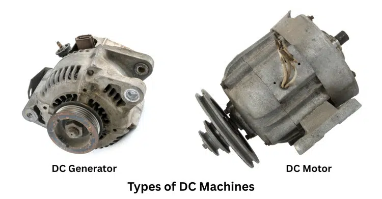
Types of DC Machines: Diagram and Applications
Direct current (DC) machines are quiet machines that run everything from heavy industrial systems to smart gadgets in your home. These essential electric machines lie at the heart of technological progress, efficiently converting electrical energy into mechanical motion and sparking innovation across countless industries. But what makes DC machines so vital, and how do the different types of DC machines impact our daily lives and modern engineering?
This article is your all-in-one guide to the different types of DC machines, crafted to help students, hobbyists, and professionals alike. Here, you’ll uncover the main types of DC motor and DC generator, and learn their unique roles through easy-to-follow diagrams.
Types of DC Machines
To fully grasp the operation and utility of direct current technology, we must first examine the broad classification of DC machine systems. These electromechanical systems are not one-size-fits-all; they are categorized by function—specifically, whether they convert mechanical energy to electrical energy or vice versa.
Broadly speaking, the family of DC machines is divided into two primary categories:
- DC Generators
- DC Motors
This fundamental division helps engineers and technicians select the right equipment for specific power conversion tasks. Let’s break down these two main categories before diving deeper into the specific sub-types.
DC Generators
A DC generator is a type of electrical machine that transforms mechanical energy into electrical energy. The DC generator working principle is based on electromagnetic induction: when a conductor moves through a magnetic field, it cuts across magnetic flux lines, which induces an electromotive force (EMF). This EMF generates the required direct current electricity.
In the classification of DC generator systems, you will find machines that power everything from portable welding equipment to large-scale industrial power systems. They are essential where a stable DC supply is required, and AC mains power is unavailable or unsuitable.
DC Motors
On the other hand, a DC motor is designed to change electrical energy into mechanical movement. When a electric current flows through conductors placed in a magnetic field, a force acts on the conductors, causing the motor’s shaft to rotate.
The classification of DC motors covers a wide variety of types used across many industries and devices. From small electric shaver motors to powerful traction motors in electric trains, DC motors offer versatile solutions thanks to their notable features, such as strong starting torque and straightforward speed regulation.
Types of DC Generators
Once a DC machine is identified as a generator, its classification goes deeper. The method used to supply current to the field windings determines the generator’s specific type and its performance characteristics.
This distinction is crucial for understanding where and how each generator is used in power generation. The classification of DC generator models is primarily based on this excitation method.
We can divide DC generators into two main categories:
- Separately Excited DC Generators
- Self-Excited DC Generators
Let’s explore these types of DC machines in detail, complete with diagrams and examples to illustrate their function.
Separately Excited DC Generator
As the name suggests, a separately excited DC generator has its field windings energized by an independent external DC source. This source could be a battery, a separate small generator, or a rectifier. The key feature is that the field winding circuit is electrically isolated from the armature circuit.
Working Principle and Features
The working principle of a DC generator of this type is straightforward.
- An external DC voltage is applied to the field windings, producing a strong, constant magnetic field.
- A prime mover (like a diesel engine or turbine) rotates the armature conductors within this magnetic field.
- Due to electromagnetic induction, an electromotive force (EMF) is induced in the armature conductors.
- This generated EMF drives current through the external load connected across the armature terminals.
Key Features:
- Excellent Voltage Control: Since the field flux is independent of the load current, the output voltage can be controlled over a wide range by simply adjusting the external excitation voltage. This provides very stable voltage regulation.
- Independent Operation: The generator’s output is not affected by fluctuations in its own armature circuit, making it reliable for sensitive applications.
- Requires External Power: Its main drawback is the need for a separate DC power source, which can add to the cost and complexity of the setup.
Example: These generators are commonly used in laboratories for testing and in specific industrial applications, such as Ward-Leonard speed-control systems, where precise and wide-ranging voltage control is essential.
Self-Excited DC Generator
Unlike a separately excited DC generator, a self-excited DC generator uses its own output to energize its field windings. The current required to create the magnetic field is drawn directly from the armature. For this to work, the generator relies on the small residual magnetism in the field poles.
When the armature first starts to rotate, this weak residual magnetic field induces a small EMF. This EMF drives a small current through the field windings, which in turn strengthens the magnetic field. This process continues, and the voltage builds up until it reaches its rated value.
Self-excited generators are further classified based on how the field windings are connected to the armature. There are three primary types:
- Shunt Generator
- Series Generator
- Compound Generator
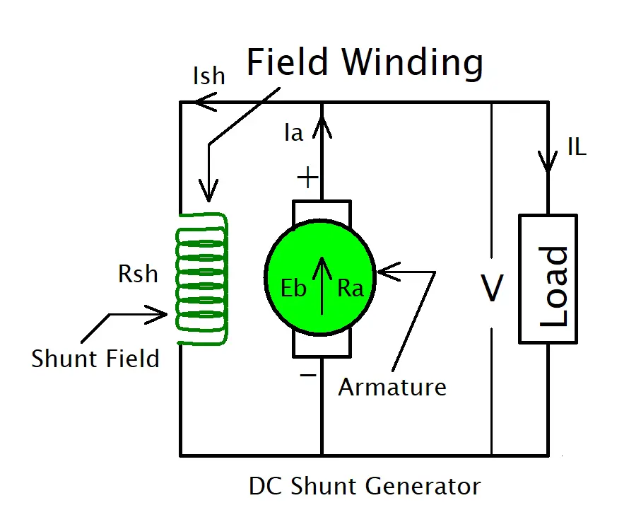
DC Shunt Generator
In a DC shunt generator, the field windings are connected in parallel (or “in shunt”) with the armature conductors. This means the field winding receives the full generator output voltage.
Working Principle and Features:
The shunt field winding consists of a large number of thin-wire turns, which give it high resistance. This ensures it draws only a small portion of the armature current, leaving the majority for the external load.
As the load increases, the terminal voltage tends to drop slightly due to the armature voltage drop. This slight voltage drop also reduces the field current, further decreasing the voltage. This characteristic makes them unsuitable for applications with highly fluctuating loads.
Example: Due to their relatively constant output voltage, shunt generators are ideal for applications such as battery charging, electroplating, and excitation of larger alternators.
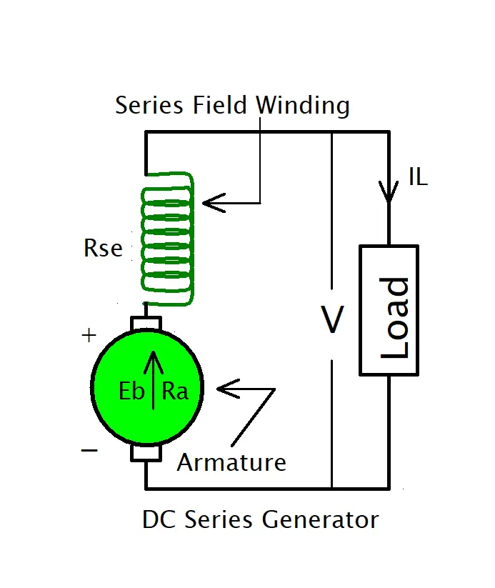
DC Series Generator
In a DC series generator, the field winding is connected in series with the armature conductors. The entire armature current flows through both the field winding and the load.
Working Principle and Features
To handle the full load current, the series field winding is designed with a few turns of thick wire, resulting in very low resistance. In this configuration, the field flux is directly proportional to the load current.
At no load, there is almost no field flux (only residual magnetism), so the output voltage is very low. As the load current increases, the field flux strengthens, and the output voltage rises. This rising voltage characteristic is unique among DC generators.
Example: Because their output voltage increases with load, series generators are used in specific applications, such as DC arc welding (where a rising voltage helps stabilize the arc) and as boosters in DC distribution systems to compensate for line voltage drops.
DC Compound Generator
A compound generator features two distinct field windings—series and shunt—mounted on the same pole core. This combination allows the generator to have characteristics from both types, providing a powerful way to tailor its voltage regulation. The shunt winding provides a base level of magnetic flux, while the series winding’s flux changes with the load.
Compound generators are further divided into two types based on the connection of the shunt winding:
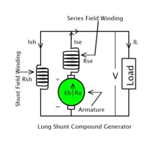
Long-Shunt Compound Generator
In this configuration, the shunt field winding is connected in parallel with the combination of the armature and the series field winding.
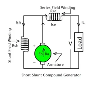
Short-Shunt Compound Generator
Here, the shunt field winding is connected in parallel only with the armature. The series winding is outside this parallel connection, carrying only the load current.
The behavior of a compound generator also depends on whether the magnetic flux from the series winding aids or opposes the flux from the shunt winding.
- Cumulative Compound: The series field flux aids the shunt field flux. This can be designed to create a flat voltage characteristic (flat-compounded) or a rising one (over-compounded). They are the most common type and are used for heavy-duty power generation in applications like powering elevators, conveyors, and heavy machine tools.
- Differential Compound: The series field flux opposes the shunt field flux. This results in a significant voltage drop as the load increases. Due to their unstable nature, they have very few practical applications but are sometimes used for specific purposes, such as arc welding.
Types of DC Motors
Once a DC machine is identified as a motor, its classification goes deeper. The method used to supply current to the field windings determines the motor’s specific type and its performance characteristics. This distinction is crucial for understanding where and how each motor is used in mechanical systems. The classification of DC motor models is primarily based on this excitation method.
We can divide DC motors into two main categories based on how their field is energized:
- Separately Excited DC Motors
- Self-Excited DC Motors
Let’s explore these types of DC motors in detail, complete with diagrams and examples that illustrate their function.
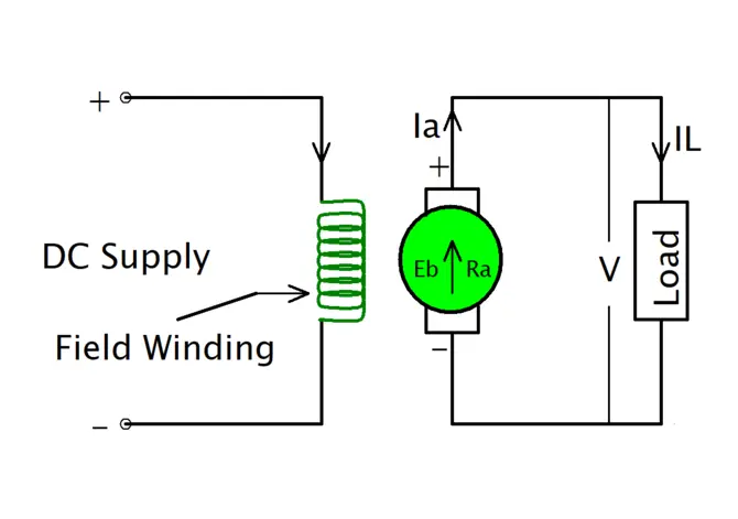
Separately Excited DC Motor
As the name suggests, a separately excited DC motor has its field windings energized by an independent external DC source. This source could be a battery, a dedicated power supply, or a rectifier. The key feature is that the field winding circuit is electrically isolated from the armature circuit.
Working Principle and Features
The operation of this type of DC motor is highly controllable.
- An external DC voltage is applied to the field windings, producing a strong, constant magnetic field.
- A separate voltage is applied to the armature, driving current through its conductors.
- The interaction between the magnetic field and the armature current produces a force (torque), causing the armature to rotate.
Key Features:
- Excellent Speed Control: Since the field flux operates independently of the armature current, the motor’s speed can be adjusted across a wide range—both above and below its rated speed—by modifying either the armature voltage or the field current.
- Independent Operation: The torque and speed characteristics are not directly linked, providing predictable, stable performance ideal for precision control systems.
- Requires External Power: Its main drawback is the need for a separate DC power source for the field, which adds to the cost and complexity of the setup.
These electric motors are commonly used in applications where precise speed control is the top priority, such as in paper mills, steel rolling mills, and high-performance machine tools, including CNC machines.
Self-Excited DC Motor
Unlike a separately excited motor, a self-excited DC motor uses the same power source for both its armature and its field windings. The current required to create the magnetic field is drawn directly from the main supply. This is the more common configuration for general-purpose motor applications.
Self-excited motors are further classified based on how the field windings are connected to the armature. There are three primary types:
- Shunt Motor
- Series Motor
- Compound Motor
DC Shunt Motor
In a DC shunt motor, the field windings are connected in parallel (or “in shunt”) with the armature conductors. This means the field winding is exposed to the full supply voltage.
Working Principle and Features
The shunt field winding consists of a large number of thin-wire turns, giving it high resistance. This design ensures it draws only a small portion of the total current, leaving the majority to power the armature.
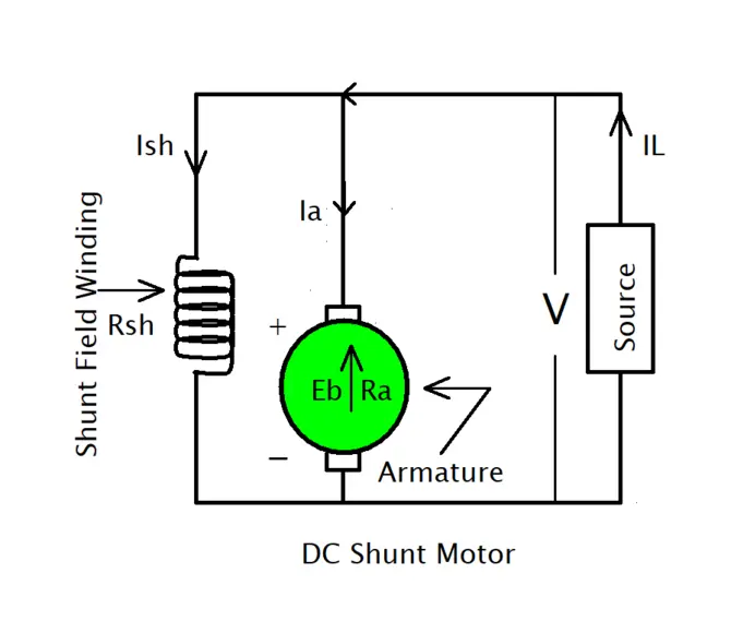
The motor’s speed is primarily determined by the back EMF generated in the armature. As mechanical load increases, the motor slows slightly, reducing back EMF and allowing more current to flow, thereby increasing torque to meet the demand.
Key Features:
- Constant Speed: A shunt motor is known for its excellent speed regulation, maintaining a relatively constant speed from no-load to full-load.
- Moderate Starting Torque: It provides a decent starting torque, typically around 150% of its full-load torque, making it suitable for loads that don’t require a massive initial push.
Example: Due to their stable speed, shunt DC motor types are ideal for driving machine tools like lathes and grinders, as well as fans, blowers, and conveyor belts that require consistent operational speed.
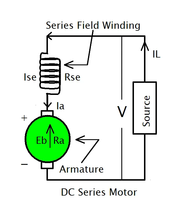
DC Series Motor
In a DC series motor, the field winding is connected in series with the armature conductors. The entire motor current flows through both the field winding and the armature.
Working Principle and Features
To handle the full motor current, the series field winding is designed with a few turns of thick wire, giving it very low electric resistance. In this configuration, the field flux is directly proportional to the armature current.
Because torque is proportional to both field flux and armature current, the torque in a series motor is proportional to the square of the current (before magnetic saturation). This results in extremely high torque at low speeds.
Key Features:
- Very High Starting Torque: This is the defining characteristic of a series motor, making it perfect for starting heavy, high-inertia loads.
- Variable Speed: Speed varies dramatically with load. It runs slowly under heavy load and can speed up to dangerous levels when the load is removed. For this reason, a series motor should never be run without a load.
Example: Because of their high starting torque, series motors are the go-to choice for traction applications such as electric trains and trams, as well as for cranes, hoists, and automotive starter motors.
DC Compound Motor
A compound motor has both a series field winding and a shunt field winding. This combination allows the motor to have characteristics from both types, offering a balance between the high starting torque of a series motor and the stable speed regulation of a shunt motor.
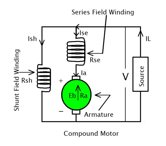
Compound motors are further divided into two types based on the connection of the shunt winding:
Long-Shunt Compound Motor
In this configuration, the shunt field winding is connected in parallel with the combination of the armature and the series field winding. It is “long” because the shunt connection spans across both the series field and the armature.
Short-Shunt Compound Motor
Here, the shunt field winding is connected in parallel only with the armature. The series winding is outside this parallel connection, in series with the main power line. It is “short” because the shunt connection only bridges the armature.
The behavior of these electromechanical devices also depends on whether the magnetic flux from the series winding aids or opposes the flux from the shunt winding.
- Cumulative Compound: The series field flux aids the shunt field flux. This results in high starting torque and good speed regulation, preventing the motor from running away at no load. This is the most common type of compound motor. They are used for applications with sudden heavy loads, such as rolling mills, presses, shears, and elevators.
- Differential Compound: The series field flux opposes the shunt field flux. This causes the motor’s speed to increase with increasing load, leading to instability. Due to this characteristic, they have very few practical applications and are generally avoided.
Application of DC Machine
The capability of direct current machines to deliver adjustable speeds and generate high torque makes them useful for numerous industrial applications. The main uses of direct current machines consist of the following applications:
Application of DC Motor
- Electric Traction: This type of machine operates within trams with electric trains and trolleys since it provides high starting torque and variable speed requirements.
- Lifting and Hoisting: These machines operate in lifting systems, including cranes, gates, and hoists, because accurate speed regulation and torque control needs exist.
- Industrial Machinery: direct current motors power conveyors, rolling mills, and numerous other machinery that need adjustable operating speeds.
- Fans and Blowers: Shunt and compound DC motors operate fans, blowers, and ventilation systems because these devices need a steady-speed operation.
Application of DC Generator
- Battery Charging: Various industries, alongside electric vehicles, utilize direct current generators as their primary choice for battery charging systems.
- Power Supply: These devices distribute direct current energy for particular systems that do not operate with alternating current power.
- Laboratory Applications: Laboratory investigations that need a managed DC power source use direct current generators as their primary power supply.
Characteristics of DC Machine
A direct current machine’s various characteristics depend on its design type and operational mode. The following list presents the most crucial machine characteristics.
- Torque-Speed Characteristics: The different torque-speed behaviors of commutator motors depend on the type of motor design. Series motors show an increasing torque when motor speed decreases, yet shunt motors demonstrate stable speed performance despite changing power loads.
- Speed-Armature Current Characteristics: In shunt and compound motors, a direct current motor’s speed aligns inversely to the armature current, whereas series motors display a proportional relationship between speed and current.
- Efficiency: Commutator machine operational efficiency depends on minimizing losses in copper material, core materials, and mechanical elements. A DC machine designed properly with reduced losses generates higher operational efficiency.
- Commutation: A direct current machine needs proper communication to run smoothly. The connection between the machine and the power supply creates sparking while causing damage to brush wear, resulting in reduced system performance.
Conclusion
In conclusion, the world of electromechanical engineering relies heavily on the distinct capabilities of Direct Current machines. From generating stable power to providing powerful mechanical drive, the various types of DC machines, with diagrams and uses, each fill a specific and critical role. Understanding the fundamental differences in their construction—whether shunt, series, or compound—unlocks their unique performance characteristics.
Ultimately, selecting a DC machine is not a one-size-fits-all decision. It demands a clear analysis of the application’s requirements. By grasping the principles outlined here, engineers, technicians, and students can confidently choose the right machine for the job, ensuring efficiency, reliability, and safety in any system they design or maintain.
FAQ
What is the purpose of a compound DC motor?
Compound motors are used where both high starting torque and constant speed are required.
What are the components of a DC machine?
Key components include the armature, field winding, commutator, brushes, and yoke.
What is the difference between a DC motor and a DC generator?
A DC motor converts electrical energy into mechanical energy, while a DC generator does the reverse.
What is the difference between a cumulative and differential compound motor?
In a cumulative compound motor, the series and shunt fields aid each other, while in a differential compound motor, they oppose each other.
What is the importance of speed control in DC motors?
Speed control allows DC motors to be used in applications requiring variable speeds, such as elevators and conveyors.
What is the application of a DC motor in robotics?
DC motors are used in robotics for precise motion control and high torque requirements.
I am an electrical engineer and also a blogger. I write informative blog posts on topics related to electrical and electronics engineering. If you are interested in these topics, you are welcome to my site to read these articles.