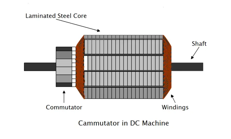
Commutator in DC Machine
The commutator is a crucial component in a DC machine, playing a vital role in the machine’s smooth operation and efficient conversion of electrical energy. It acts as an interface between the armature winding and the external circuit, controlling current flow and thereby generating continuous torque in the direction of the rotor. Its design and functionality provide high efficiency and reliability in both DC motors and generators. This article provides all the essential information about the commutator in DC machine.
What is Commutator
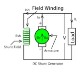
The commutator is a crucial component of a DC machine, converting electrical energy into mechanical energy and vice versa. Together with the armature, it forms the armature-commutator system, which ensures that the electric current flows in the correct direction.
The commutator is cylindrical, made of insulated copper segments. Its primary function is to produce continuous torque by reversing the direction of the current in the armature winding. Thus, the armature commutator is essential for the efficient operation of DC motors and generators.
Construction of Commutator in DC Machine
The commutator is an essential component of a DC machine, whether it is a motor or a generator. It plays a vital role in the smooth operation of the machine and efficient energy conversion. The commutator has a complex yet precisely engineered structure that helps it establish a reliable connection between the external circuit and the armature winding. Let’s understand the commutator’s manufacturing process, the materials used, and its design in detail.
Design and Structure of the Commutator
The commutator is cylindrical and mounted on the armature shaft. It is composed of several copper segments, which is why it is also called a commutator segment. These segments are mounted on the shaft so they are completely insulated from each other. Due to its cylindrical design, it acts as an effective rotary switch, controlling the direction of current flow as the rotor rotates. Each copper segment is connected to one end of an armature coil.
Components of Commutator
High-quality materials are used in the commutator’s construction to withstand high temperatures and mechanical stress during operation.
- Copper Segments: The commutator segments are made from hard-drawn copper. Copper is an excellent electrical conductor and also possesses good thermal resistance. These segments are cut into a wedge or V shape so they fit together to form a circular structure.
- Insulation: Insulating material is used between the segments and to separate them from the shaft. Typically, mica is used for insulation. Mica is an excellent insulator that retains its properties even at high temperatures. Layers of mica approximately 0.5 to 1 mm thick are placed between the segments.
Manufacturing process
Let’s understand the various stages of commutator manufacturing step by step:
- Joining the segments: First, the copper segments and mica layers are joined together one by one to form a cylindrical shape.
- V-groove formation:The copper segments are manufactured in such a way that V-shaped grooves are formed at the ends of the commutator. These grooves help securely mount it to the hub or sleeve.
- Clamping and Baking: The entire assembly is tightly secured using V-rings and clamping rings. Following this, it is baked at a high temperature to harden the insulating material and eliminate any remaining moisture.
- Machining and Finishing: After baking, the commutator’s outer surface is smoothed on a lathe to make it suitable for brush contact surface.
Commutator Function
The commutator acts like a split ring and is sometimes referred to as such. As the armature rotates, the carbon brushes slide over these copper segments. As the brushes move from one segment to the next, the direction of the current in the armature coil reverses. This process helps maintain the rotor’s torque in a constant direction, allowing the motor to rotate continuously. It is the function of the rotary switch that converts AC to DC (in the case of a generator) or DC to AC (for the armature of a motor).
Role of Commutator in DC Motor
The DC motor is a marvel of engineering, converting electrical energy into mechanical energy. Many components work together in this process, but the armature commutator plays the most crucial and decisive role. It is often called the “heart” of the motor because continuous rotation would be impossible without it. Let’s explore the role and working principle of the commutator in a DC motor in detail.
Function of the Commutator in a DC Motor
In a DC motor, the commutator controls the direction of current in the armature coil. As the armature rotates between the magnetic poles, it requires a continuous torque in one direction. As the armature coil crosses the neutral plane of the magnetic field, the commutator reverses the direction of the current. If the current direction were not reversed, the armature would rotate only half a turn and then return to its original position, failing to complete a full rotation.
It is a rotary switch that reverses the current direction as it rotates. It ensures that the magnetic force always acts in the same direction, allowing the motor to rotate continuously. This process is called ‘commutation’.
It’s interesting to note that, although we call it a DC motor, the current flowing through the armature is actually alternating to maintain torque. While the external circuit uses direct current (DC) to power the motor, the split ring action of the commutator converts this into alternating current (AC) inside the armature.
Role of Commutator in DC Generator
A DC generator is a helpful device in electrical engineering that converts mechanical energy into electrical energy. Although this machine has several components, the commutator is the most distinctive. It is often called a “mechanical rectifier” because it converts the AC (alternating current) generated within the generator into DC power supply (direct current) for the external circuit.
Function of Commutator in a DC Generator
When the armature of a DC generator rotates in a magnetic field, an electromotive force (EMF) is induced in the armature conductors according to Faraday’s law of electromagnetic induction. The current generated within the armature is alternating. However, since it is a DC generator, we require unidirectional, or direct, current at its output terminals.
Here, the commutator plays its crucial role. It acts like a segment switch, reversing the connection to the external circuit as the armature coil rotates. It ensures that the current in the external load always flows in the same direction, even though the current inside the armature constantly reverses.
The commutator is mounted on the armature shaft and is connected to the armature winding. This entire combination is called the armature commutator assembly. Each end of the armature coil is connected to a segment of the commutator. As the armature rotates, the commutator rotates with it. Stationary carbon brushes slide against the commutator and transfer the current to the external circuit. This precise combination of the armature and commutator is what allows the generator to deliver power efficiently.
The output from the split ring commutator is not pure DC but pulsating DC. However, it always flows in the same direction. The more armature coils and commutator segments a generator has, the smoother and more continuous the output will be. Modern generators use a segmented commutator design with many segments to minimize ripple and produce a more stable DC output.
Types of Commutator in DC Machine
The design and construction of the armature commutator in a DC machine vary with size, voltage, and operating conditions. Commutators are primarily classified into three categories based on their manufacturing method and design:
V-Ring Commutator
It is the most common and traditional commutator type, widely used in small- to medium-sized DC machines.
- Construction: It is made by joining copper segments and mica layers. V-shaped grooves are made at the ends of the segments, into which micanite rings (V-rings) are fitted. The entire assembly is then securely fastened with steel clamping rings. This design provides structural integrity to the armature commutator assembly.
- Operating Principle: This device functions as a reliable rotary switch, maintaining its structural integrity even at high speeds and temperatures. The V-ring design securely holds the segments in place against centrifugal force.
Shrink-Ring Commutator
It is a current modern design used specifically in high-speed DC machines.
- Construction: In this type of commutator, copper segments are assembled into a cylindrical structure, and a fiberglass or other high-tensile ring is heated and fitted onto them. Upon cooling, this ring shrinks and exerts intense pressure on the segments, holding them firmly in place.
- Working principle: This design creates a highly robust armature commutator that can withstand centrifugal forces even at very high speeds. Its compact structure makes it ideal for high-performance applications.
- Use: It is used in traction motors, rolling mill motors, and other heavy-duty industrial applications that require high-speed rotation.
Dovetail Commutator
It is another robust type of commutator, which is an advanced version of the V-ring design.
- Construction: Dovetail or T-shaped grooves are made in the copper segments. These grooves are then interlocked with steel rings to strengthen the connection. This structure provides stability to the segments in both radial and axial directions.
- Working principle: This design uses a robust rotary switch that delivers excellent performance even under high torque and demanding operating conditions.
Application of Commutator
Without the armature commutator, DC motors and generators would be unable to function effectively. The applications of commutators are not limited to large industries; they are also crucial in many devices we use in our daily lives.
- In DC motors: The most prominent and widespread application of a commutator is in DC motors. For any DC motor to operate smoothly, the torque acting on the rotor (the rotating part) must always be in the same direction.
- In Universal Motors: Have you ever wondered how your home’s mixer-grinder, drill machine, or vacuum cleaner works? Most of these appliances use a ‘universal motor’. These motors also utilize an armature commutator system.
- In rectification: The commutator in a DC generator acts as a mechanical rectifier. It converts the AC generated inside the armature into DC for the external circuit.
- In automotive motors: Every car, truck, or bus requires a powerful electric motor to start, which is called a “self-starter.” It is a special type of DC series motor. It also uses a rotary switch.
- In electric traction: Traction motors used in railways and electric trains require high torque and speed control to pull heavy loads. In traditional DC traction systems, the current is controlled using an armature commutator assembly.
Limitation of Commutator
In DC machines, the commutator performs the crucial function of rectifying the current and providing continuous torque to the motor. However, despite its usefulness, the commutator has some severe mechanical and electrical limitations. These limitations affect the efficiency, speed, and maintenance of the machines. Let’s examine the main limitations and challenges of the commutator in detail.
Sparking and Friction
The biggest problem with commutators is sparking. When the carbon brushes move from one segment to another, sparks are generated as the contact is broken and re-established. This arc not only causes energy loss but also generates heat. The commutator essentially acts like a high-speed segment switch. When the current is high, sparking at the edges of the brushes during switching increases, which can damage the commutator surface and cause pitting.
Speed Limitations
As the speed of the armature commutator increases, the centrifugal force acting on the copper segments also increases. If the speed becomes too high, the commutator segments can be thrown out of place, potentially leading to complete machine failure.
Voltage and current limits
A thin layer of mica is present between the segments of the commutator. If the voltage between two segments suddenly increases (to more than approximately 30-40 volts), a flashover can occur between the segments, which can short-circuit the armature commutator.
The contact area between the brushes and the commutator is limited, so they cannot carry very high currents.
High Maintenance
The wear and tear of the carbon brushes generates carbon dust, which can interfere with the commutator’s switching action and cause short circuits. Over time, the commutator surface becomes rough and requires periodic “skimming” or resurfacing. Therefore, compared to AC motors, commutator DC motors require significantly more maintenance.
Conclusion
In conclusion, while the commutator in a DC machine is an essential component for achieving continuous rotation and energy conversion, its inherent limitations cannot be overlooked. Issues such as sparking, high maintenance requirements due to mechanical wear, and operational constraints on speed and voltage significantly impact the machine’s overall performance and reliability. Understanding these drawbacks is crucial for engineers and technicians, as it allows for better maintenance strategies and informs the decision to adopt more advanced, brushless technologies in applications where efficiency and durability are paramount. Ultimately, acknowledging the limitations of the commutator is the first step toward optimizing DC machine performance and exploring superior alternatives.
FAQ
What are the properties of a commutator?
- Made of copper segments.
- Insulated with mica.
- Cylindrical in shape.
- Acts as a rotary switch.
- Requires regular maintenance.
What is the difference between commutators and slip rings?
- Commutator: Reverses current, segmented, used in DC machines.
- Slip Ring: Transfers current, smooth, used in AC machines.
What is motor commutation?
The process of reversing current direction in the armature windings of a DC motor to maintain continuous torque and rotation. It is achieved using a commutator and brushes.
What is the meaning of commutator?
A commutator is a rotary switch in DC machines that reverses current direction in the armature windings, enabling continuous rotation and energy conversion.
I am an electrical engineer and also a blogger. I write informative blog posts on topics related to electrical and electronics engineering. If you are interested in these topics, you are welcome to my site to read these articles.