DC Generator Working Principle
Imagine having a machine that, simply by being rotated (performing mechanical work), begins to generate a perfectly steady and continuous flow of electricity (Direct Current). In the realm of electrical engineering, this remarkable device is known as a DC Generator.
Stepping away slightly from technical jargon and attempting to understand this in simpler terms, you will discover that it is a device capable of directly converting any form of mechanical energy into electrical energy (DC). You can visualize it this way: you supply mechanical power—perhaps from an engine—at one end, and in return, it delivers a perfectly smooth stream of DC power at the other.
If you are an electrical engineer or a technical student, understanding the working principle of a DC generator is not merely a syllabus requirement; it is essential to grasp the very ‘soul’ of this machine.
To be honest, without clarifying its core fundamentals, you can never truly delve into its design, performance, or troubleshooting. In this vast world of machinery, understanding where it fits in—and the actual science underpinning it—is not just academic knowledge; it constitutes an absolutely vital and practical wisdom for every technical professional.

What is the DC Generator Working Principle?
When it comes to the working mechanism or operating principles of a DC generator, its entire foundation rests upon the science of Electromagnetic Induction. To gain a deeper understanding of the underlying science behind this, let us first explore the fundamental laws that make it possible:
Electromagnetic Induction Principle:
To understand this, imagine that when we rapidly rotate a conductor—such as a copper coil—within a magnetic field, the coil moves forward as it cuts across the magnetic field lines in that region. At that very instant, a voltage, or Electromotive Force (EMF), is spontaneously generated within the conductor. In the realm of science, this fascinating process is known as ‘Electromagnetic Induction.’
In this remarkable method of electricity generation, DC machines employ external power—specifically, mechanical energy from a turbine or engine—to continuously rotate the armature between magnets; in return, the machine generates and delivers electricity.
Faraday’s Law of Electromagnetic Induction:
The real ‘magic’ behind the operation of a DC generator lies hidden in Michael Faraday’s laws of electromagnetic induction. Let’s understand this from a practical perspective, moving slightly beyond the textbook definition:
- Faraday’s First Law: To understand this, consider that whenever the magnetic flux surrounding a conductor changes or fluctuates, an EMF—that is, a voltage—is automatically induced within that conductor. Simply put, changes occurring within a magnetic field generate electricity!
- Faraday’s Second Law: Now, the question arises: how strong will this induced voltage be? This law of Faraday states that this depends directly on the rate at which the magnetic flux is changing (the rate of change of flux). In other words, the faster the speed of the change in flux, the stronger the induced EMF (voltage) will be.
Key Components Involved in the Working of a DC Generator
To fully understand how a DC generator actually works, we must examine its ‘key players’—the components—one by one. Each part of the generator plays a specific role in generating electricity. Let’s understand these key components in simpler terms:
- (Armature): This is the part of the generator that continuously rotates. Structurally, it consists of a cylindrical core around which copper coils are wound. When this armature rotates rapidly in a strong magnetic field, its coils cut through the magnetic field lines. It is precisely this motion that induces an electromotive force (EMF)—or voltage—within these coils.
- (Field Windings): The field windings generate a very powerful, stable magnetic field inside the generator. These wires are wound around the generator’s poles. As soon as current flows through them, they transform into a powerful electromagnet. This is the very magnetic field—that magical force—which our armature cuts through as it rotates to generate electricity.
- (Commutator): Commutators are the most ingenious and distinctive components of a DC generator. The current generated by the rotation of the armature is, in reality, Alternating Current (AC). The commutator functions as a ‘converter’—or a mechanical rectifier—that instantly transforms the AC current from the armature into Direct Current (DC). It is constructed by joining together numerous small segments of copper.
- (Brushes): Brushes are typically made of carbon or graphite. You can think of them as acting like a ‘bridge.’ They rest lightly against the rapidly rotating commutator. Their role is one of great responsibility—to collect the DC generated by the commutator and safely transmit it to the external circuit or your load, without producing any sparks.
Step-by-Step Explanation of the Operating Principle of a DC Generator
Now that you are familiar with the key components (parts) of a generator, let’s examine exactly how a DC machine operates and how it converts mechanical energy into electrical energy, step by step:
Conversion of Mechanical Energy to Electrical Energy:
The story begins with an external force, which we refer to as the ‘Prime Mover’—this could be a diesel engine or a turbine. With its aid, we rotate the generator’s armature at high speed. This, quite simply, constitutes the mechanical energy we supply. As this armature spins rapidly within the powerful magnetic field generated by the field windings, the actual process of electricity generation commences.
Role of Magnetic Fields and Motion:
To understand the working mechanism of a DC generator in depth, consider that as the armature rotates between the North and South poles, the wires (conductors) housed within it move forward, cutting through the magnetic flux lines in the field. According to Faraday’s Law of Electromagnetic Induction, it is precisely this “cutting” action that induces a voltage (EMF) within those wires. The fundamental principle is simple: the faster the armature rotates, and the stronger the magnetic field, the greater and more substantial the voltage generated will be.
Generation of Unidirectional Current:
The fascinating thing is that the current generated inside the armature repeatedly reverses its direction—meaning it is, in fact, an AC! However, what we actually require is a Direct Current (DC) that flows in a single, consistent direction. This is precisely where our clever component—the Commutator—makes its entrance. The moment the armature completes half a rotation and attempts to reverse the current, the commutator instantly switches its connection to the brushes. Thanks to this ingenious maneuver, the current in the external circuit remains unidirectional. Thus, by the time internal AC reaches the external wires, it has been transformed into a steady, unidirectional DC.
Role of the Commutator in Ensuring DC Output
You might be surprised to learn that the current generated within the armature of a DC generator is, in reality, alternating current (AC) by nature! The entire responsibility for converting this into direct current (DC) rests upon the shoulders of the commutator. To put it in very simple terms, the commutator functions as a smart mechanical rectifier inside the machine.
How the Commutator Converts AC into DC:
Just imagine this for a moment: when the armature coil completes a half-cycle of rotation within the magnetic field, the direction of current through it reverses. But here lies the real trick! The small segments of the commutator rotate along with the armature at precisely the same speed. The design of the commutator is so ingenious that, even though the current within the coil reverses its direction, its rotation ensures that the current flowing through the external wires always continues to flow smoothly in a single, unidirectional path.
We have merely caught a brief glimpse of the commutator here, but the actual science behind it is even more fascinating. If you wish to delve deeper into commutators and understand their intricacies, be sure to read our detailed article, Commutator in DC Machine.
Importance of Brushes:
In this entire power generation system, the role of brushes—made from carbon or graphite—is nothing short of that of a silent hero. These brushes remain completely stationary within the generator, yet they maintain constant contact with the rapidly rotating commutator. You can visualize them as a stationary ‘bridge.’ Their primary function is to safely collect the unidirectional current (DC) generated by the commutator and deliver it to the external circuit—or your load—without any sparking or interruption.
Factors Affecting the Working of a DC Generator
The actual amount of electricity (Voltage/EMF) a DC generator generates depends primarily on three key factors. Rather than approaching this theoretically, let’s understand it from a slightly more practical perspective:
- Speed of Rotation: Theoretical principles state that the faster a generator’s armature rotates, the more rapidly it cuts through the magnetic flux. The fundamental principle of electromagnetic induction is simple: the higher the speed at which the flux is cut, the greater the magnitude of the generated voltage (EMF).
- Strength of the Magnetic Field: If you look at it from a practical standpoint, you will realize that the more powerful the magnetic field generated by the field poles, the greater the number of magnetic lines available to cut through our armature conductors. Simply put, increasing the magnetic field strength increases your output power.
- Number of Conductors in the Armature: In practice, it is also observed that the greater the number of turns or conductors within the copper coils embedded in the armature core, the more substantial the electricity generation will be. Essentially, the minute voltages induced in each conductor combine to form a cohesive unit, enabling the generator to deliver a robust, powerful final voltage.
Practical Demonstration of the Working Principle
Reading about the working mechanism of a DC generator in books is one thing, but truly understanding it requires mental visualization. So, let’s visualize this entire process through a very simple example and a brief thought experiment.
Single Loop Generator Example
Just imagine that you possess a very powerful magnet (a permanent magnet) with two poles—North and South. A very strong, yet invisible, magnetic field exists between these two poles. Now, imagine that you have placed a rectangular loop of copper wire right in the center of this magnetic field. For clarity, we can consider this our most basic armature.
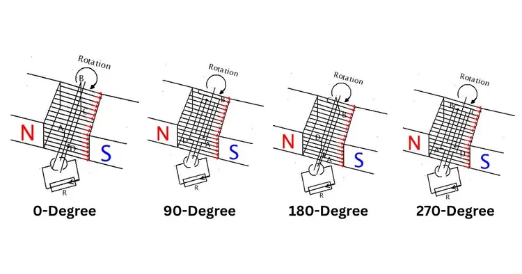
Now, the moment you grasp a handle and start rotating this loop, watch the magic that unfolds inside:
- 0-Degree Position: Initially, when the loop is exactly parallel to the magnetic lines, no flux is cut. At this moment, the voltage induced within the loop (Induced EMF) is precisely zero.
- 90-Degree Position: As the loop rotates to the 90-degree mark, its wires begin to cut through the magnetic field lines at a precise right angle (perpendicular). According to Faraday’s Law, the rate at which the flux is cut is at its maximum at this point. Consequently, the generated voltage also reaches its absolute peak level.
- The Journey from 180 to 270 Degrees: As the loop rotates slightly further, the voltage drops back to zero, then at 270 degrees reaches its maximum value in the opposite direction.
The current generated by all this commotion is, in reality, an Alternating Current (AC). However, the real magic happens when we attach a Split-Ring Commutator to the ends of this loop. This clever device reverses the direction of the fluctuating current, ensuring it flows in a single, unidirectional path through the external circuit. And just like that, a simple rotating loop—driven by mechanical rotation—delivers to you a pure, unadulterated Direct Current (DC)!
A simple experiment that can be done at home.
You can personally test this principle in practice using a small toy motor. Take my advice—you should definitely give it a try!
Take a small DC motor (the kind that typically runs on a battery) and connect its two wires to a small LED light. Now, simply use your hands to spin the motor’s shaft rapidly. You will be amazed to see that the LED light instantly lights up!
So, what exactly happened here? In reality, the motor is operating in reverse. As soon as you spun the shaft (thereby imparting mechanical energy to it), the internal coils cut through the magnetic field and instantly generated electricity (electrical energy), causing the light to glow. To put it simply, this is the most authentic, practical, and fundamental working principle of a DC generator!
Applications of the Working Principle in Real Life
Even though AC generators (alternators) dominate today’s landscape, DC generators still hold a distinct stature of their own. Thanks to certain exceptional characteristics, they remain the vital core of numerous major industries and essential equipment to this day. Wherever there is a need for an absolutely steady, fluctuation-free unidirectional current—or ‘stable power’—it is the magic of the DC generator that prevails.
Let us explore where this remarkable technology demonstrates its prowess in real-world applications:
Electroplating and Electrolytic Processes
In the chemical industry and electroplating (the process of coating metals), we require an absolutely precise and stable direct current. Just imagine: if there were even a slight fluctuation in the direction of the current, the entire chemical process could be completely disrupted! For such delicate operations, Shunt DC Generators function much like a piece of ‘smart technology.’ They deliver a perfectly uniform and stable voltage, which is considered the ideal standard for these applications.
Arc Welding
The electrical requirements for welding operations are somewhat distinct and specialized. When welding begins, there is a sudden demand for a very high current, yet the voltage must remain low. This is precisely where Differential Compound DC Generators play a crucial role. Their design is so ingenious that as soon as the load increases, they automatically reduce the voltage. The result is a superior and completely safe welding arc.
Battery Charging Stations
Charging large-capacity batteries requires a consistent, stable DC power supply. Consequently, Shunt Generators are extensively utilized in large-scale battery charging plants. Their most significant advantage is that their output voltage remains absolutely stable. This very ‘stable power’ is crucial for maintaining and enhancing the lifespan and performance of your expensive batteries.
Traction Systems and Railways
Moving and hauling heavy trains or trams from a standstill initially requires a tremendous amount of force—specifically, torque. Series DC generators and motors are extensively utilized in railway traction systems. Remarkably, as the load on these units increases, they further intensify their magnetic fields, resulting in a sudden surge in power output. Furthermore, this very principle is harnessed in smart technologies such as regenerative braking—where, upon applying the brakes, the motor instantly converts to a generator, conserving energy by feeding the residual electricity back into the system.
Laboratory and Testing Equipment
Precise experiments conducted in engineering colleges and research laboratories often require an absolutely pure and clean DC power supply. To meet this requirement, portable DC generator sets are utilized. The primary advantage of this approach is that students and scientists can easily test their machines and equipment directly on DC power, without the complications of using a rectifier.
Conclusion
In conclusion, it can be stated that the working fundamental of a DC generator rests primarily upon the solid foundation of electromagnetic induction and Faraday’s laws. This machine efficiently converts mechanical energy into electrical energy. The role of the commutator is pivotal throughout this entire process, as it transforms the alternating current (AC) generated within the armature into a steady and continuous direct current (DC).
Although AC power is ubiquitous today, the significance of DC generators remains intact for applications such as electroplating, large-scale battery charging, and specialized industrial operations. Even within the modern electrical industry—where a precise, stable, and unidirectional power supply is required—DC generators will continue to occupy a vital and indispensable position for the foreseeable future.
FAQ
-
What is the Principle of DC Generator
A electromechanical generator is a machine based on Faraday’s law of electromagnetic induction. When a conductor coil or loop is rotated inside a magnetic field, an electric current is generated in it. This current is collected in the external circuit by the commutator and brushes, which gives DC (direct current) electricity. This process is called electromagnetic induction.
-
Is DC Motor and DC Generator Same
No, a DC motor and a DC power generator are not the same. A DC motor converts electrical energy into mechanical energy, while a DC power generator converts mechanical energy into electrical energy. Both work on the same principle, but their purpose and function are different.
-
What is the Difference Between AC and DC Generator
The main difference is that an AC generator produces alternating current (AC), while a DC electrical generator produces constant current (DC). In an AC generator, the direction of the current keeps changing, while in a DC electrical generator, the current flows in one direction.
-
What is the Name of DC Generator Field
The field in a DC dynamo is called “field”, which produces a magnetic field. It can be made in two ways: the “pole field” produces a static magnetic field, and the “effective field” helps create an electric current.
-
Which Types of DC Generator is used for DC Arc Welding
For DC arc welding, the “Series Wound DC power Generator” is the best. Since there is a series connection between its stator and armature, it produces high current, which is suitable for arc welding.
I am an electrical engineer and also a blogger. I write informative blog posts on topics related to electrical and electronics engineering. If you are interested in these topics, you are welcome to my site to read these articles.

