What is AC Generator and Basics Working Principle
The synchronous generator, often called an alternator, is a fundamental player in the energy landscape, yet many remain unaware of its impact. Have you ever considered how the electricity powering your devices is generated so precisely? In this article, we will explore how AC generators work, the mechanics behind them, and discuss their operation, efficiency, and critical role in our power systems.
What is an AC Generator
A synchronous generator, also known as an AC generator, converts mechanical energy into electric power at a constant speed known as its synchronous speed. It produces AC electrical power with specific voltage and frequency requirements and is often used by large power plants and grid operators to supply electricity to their constituents. Furthermore, its rotational inertia helps maintain stability across its distribution network.
Mechanical energy is applied to the generator’s rotor by a prime mover (such as a gas turbine). At the same time, its electromagnets are excited by DC to produce an electromagnetic field that cuts across the stator windings to generate AC voltage as the rotor spins.
An Alternating Current generator relies on a regulated output control to deliver electricity at the same voltage and frequency as the grid. This complex piece of technology is essential to running the generator safely; its role includes managing generator load, controlling mechanical loads that require more power than the generator can supply, and keeping rated loads within safe limits.
An electric generator is a large, complex machine that converts mechanical energy from its prime mover into AC electric power at a constant speed. The generator’s rotor connects directly to grid frequencies, strengthening the electrical grid as a whole and increasing its capacity to accommodate fluctuating electricity demand.
A synchronous generator’s regulated output control system ensures its load can be effectively managed by matching its speed to the grid frequency and controlling the amount of electricity drawn from its rotor. Routine inspections of the generator are conducted to identify potential faults and reduce downtime or production losses.
Construction of Synchronous Generator
An alternating current generator is a key component in power generation systems. It converts mechanical energy into electrical energy, producing alternating current (AC). Alternating current generators are made up of several essential parts, each of which plays a vital role. Let us understand the names of essential alternator parts and their functions:
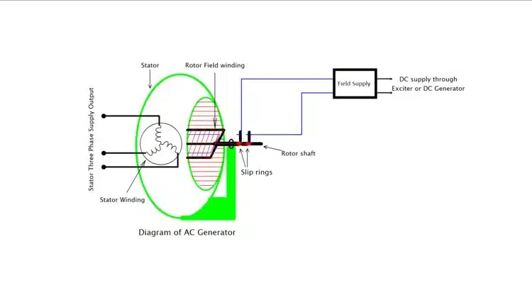
1. Stator
The stator always the stationary part of the synchronous generator. It contains a three-phase winding that creates an electromagnetic field. The stator is made of laminated sheets of high-quality steel to reduce eddy-current losses. The inner periphery of the stator has slots cut into it in which the windings are placed. The windings on the stator are placed in a set of slots, which are evenly spaced around its circular structure.
2. Rotor
The rotor is the rotating part that generates a magnetic field by DC excitation. It is rotated by a prime mover (steam or water turbine, etc.) and thereby runs at synchronous speed. It is also made of steel laminations to reduce eddy-current losses. The rotor can be either a salient-pole or a cylindrical type.
- A salient-pole rotor has protruding poles that are visible and have windings. This type is used in low-speed generators.
- The cylindrical rotor is smooth and has no protrusions, so it is also called a non-salient rotor. It is commonly used in high-speed machines. The rotor is powered by mechanical energy from a prime mover, such as a steam turbine or a diesel engine.
The rotor is energised by a DC provided by the exciter, which creates the magnetic field. The amount of current supplied to the rotor (called the field current) controls the strength of the magnetic field and, in turn, the output voltage of the generator.
3. Exciter
The exciter is a small DC generator that provides the necessary DC to the rotor windings. This current is crucial for generating the magnetic field that induces a current in the stator. Modern synchronous generators often use brushless exciters, which eliminate the need for brushes and slip rings.
4. Bearings and Shaft
The rotor is placed on a shaft, which is supported by bearings. The shaft transmits mechanical energy from the prime mover to the rotor, making it spin. The bearings reduce friction, allowing smooth rotation.
5. Cooling System
Since electrical generators generate heat during operation, a cooling system is essential to maintain the machine’s efficiency. The synchronous generator is often cooled by air or water. Air is blown over the stator and rotor, or water is circulated to absorb the heat.
6. Terminal Box and Bushings
The terminal box is connected to the stator windings. It contains terminals for connecting the generator to the external electrical network. Bushings are used to insulate electrical connections from the generator’s metal frame.
Alternator Working Principle
The working principle of AC generator is based on the electromagnetic induction function. The AC long form, alternating current, is generated to power various devices efficiently”, discovered by Michael Faraday in 1831. It converts mechanical energy into electrical energy for producing electric power. An engine supplies mechanical force to turn its crankshaft and propel it, but does not produce electricity directly; an alternator produces AC electricity to power these electronics, then converts it back to DC for use by its battery. Let’s understand its working step by step:
1. Magnetic Field Creation
When a mechanical prime mover (such as a turbine or engine) rotates the rotor, a magnetic field is generated by an exciter supplying DC to the rotor’s windings. This magnetic field rotates around the stator windings and cuts the field by the stator windings.
2. Electromagnetic Induction
According to Faraday’s law of electromagnetic induction, when the magnetic field of the rotor moves past the stationary stator coils, it induces an electromotive force (EMF) or voltage in the stator windings. The induced voltage causes electric current to flow in the stator windings when a load is applied, which produces alternating current (AC).
3. What is Synchronous Speed
For the Alternating current generator to function correctly, the rotor must rotate at a constant speed, called the synchronous speed. This speed depends on the frequency of the alternating current (AC) and the number of rotor poles. The formula gives the relationship:
\(Ns=\frac{120 \cdot f}{P}\)
Where:
- \(N_s\) is the synchronous speed (in RPM),
- \(f\) is the frequency (in Hz),
- \(P\) is the number of poles on the rotor.
The rotor speed must match the synchronous speed for the generator to operate efficiently.
4. AC Output
As the rotor spins, the magnetic field produced by the rotor poles induces an alternating voltage in the stator windings. This induced voltage produces alternating current (AC) that can be fed into the electrical grid or used to power machinery.
6. Synchronisation
The generator must maintain synchronisation with the grid. It means that the AC voltage generated by the synchronous generator must match the grid frequency. If the generator operates out of sync with the grid, it can cause equipment damage and operational instability. The generator’s output voltage can be regulated by adjusting the excitation current, ensuring it produces the desired voltage under varying load conditions.
Types of Synchronous Generator
Rotor configuration, excitation conditions, and application orientation classify AC machines. Each type is developed to serve certain operating functions, including speed, power output, and environmental conditions.
Based on Rotor Construction
Salient Pole Rotor Synchronous Generators:
- This type has the projecting poles mounted on the rotor.
- Typically used in low-speed applications (100 – 400 RPM), like a hydroelectric station, etc.
- The rotor has a large diameter and short axial length, making it easy to accommodate poles.
- It also provides improved ventilation and accommodates variable load conditions.
- Suitable for applications in which the turbine is operated at a slow speed.
Cylindrical(Non-Salient) Rotor Synchronous Generators:
- Has a smooth, cylindrical rotor embedded in slot-field windings.
- High-speed ones used 1500 to 3000 RPM (thermal and nuclear power plants).
- The rotor is mechanically stiff and balanced for high-speed rotation.
- Provides homogeneous magnetic fields, and the level of performance is more effective when the loads are constant.
Based on the Excitation Method
Separately Excited Synchronous Generator
- Requires an external DC power supply (battery or small DC generator) to excite the rotor winding.
- Provides independent control over the field current and terminal voltage.
- Rife in older generator systems and high industrial units.
Self-excited or Brushless Generator
- Includes a brushless exciter mounted on the same shaft.
- The exciter delivers AC, which is rectified and sent to the rotor.
- It transforms mechanical energy into electrical energy to generate electric power. Extensively applied in contemporary power plants for reliability and long-term service life.
Based on Shaft Orientation
Horizontal Shaft Generators
- The rotor shaft is set horizontally.
- Typical for all thermal and nuclear installations.
Vertical Shaft Generators
- The rotor shaft is vertical; it’s commonly used in hydroelectric power stations.
- Save floor space and make it easier to couple with vertical water turbines.
Emf Equation of Synchronous Generator
When the rotor of an electric generator rotates, its magnetic field cuts through the stator windings. According to Faraday’s Law of Electromagnetic Induction, an EMF (Electromotive Force) is induced in the stator windings. The magnitude of this EMF depends on:
- The number of turns in the winding.
- The speed of rotation of the rotor.
- The strength of the magnetic field.
Key Parameters in the EMF Equation
To derive the EMF equation, we need to define the following terms:
- (P): Number of poles in the generator.
- (N): Rotor speed in revolutions per minute (RPM).
- (Φ): Magnetic flux per pole (in Weber).
- ( f ): Frequency of the generated EMF (in Hertz).
- ( Z ): Total number of conductors in the stator winding.
- ( T ): Number of turns per phase.
- (kf): Form factor (accounts for the waveform shape, typically 1.11 for a sinusoidal wave).
Derivation of the EMF Equation
Step 1: Frequency of the Generated EMF
The frequency of the generated EMF is given by:
\( f = \frac{P \cdot N}{120} \)
Where:
- ( P ): Number of poles.
- ( N ): Rotor speed in RPM.
- ( 120 ): A constant derived from the relationship between speed, poles, and frequency.
Step 2: Flux Linkage
The total flux linkage in the stator winding is:
Flux Linkage per Pole \( = \Phi \cdot P\)
Step 3: Induced EMF per Conductor
The EMF induced in one conductor is given by:
\(e = \frac{d\Phi}{dt}\)
For sinusoidal flux variation, the RMS value of the EMF per conductor is:
\(e_{\text{RMS}} = 4.44 \cdot f \cdot \Phi\)
Step 4: Total EMF per Phase
The total EMF induced in a phase depends on the number of turns per phase (T):
\(E_{\text{phase}} = 4.44 \cdot f \cdot \Phi \cdot T\)
Where:
- \(( T )\): Number of turns per phase.
- \(( f )\): Frequency of the generated EMF.
- \((\Phi)\): Magnetic flux per pole.
Step 5: Line Voltage in a Three-Phase Synchronous Generator
For a three-phase AC generator, the line voltage depends on the connection type:
- Star Connection: Line voltage \((E_L)\) is:
\(E_L = \sqrt{3} \cdot E_{\text{phase}}\)
- Delta Connection: Line voltage is equal to phase voltage:
\(E_L = E_{\text{phase}}\)
4. Final EMF Equation
The final EMF equation of an alternating current generator is:
\(E_{\text{phase}} = 4.44 \cdot f \cdot \Phi \cdot T\)
Where:
- \(( 4.44 )\): A constant for sinusoidal waveforms.
- \(( f )\): Frequency of the generated EMF.
- \(( \Phi )\): Magnetic flux per pole.
- \(( T )\): Number of turns per phase.
Applications of Synchronous Generator
Because an alternator can maintain constant speed and frequency, it is widely used where electricity must be stable and steady.
Industrial Applications
Synchronous alternator are used by large industries that require continuous power. These generators are highly efficient and accurate in controlling voltage, making them suitable for heavy industrial applications such as manufacturing plants, cement factories, and steel plants.
Power Plants
The most crucial use of synchronous generators, however, is in power generation plants such as thermal, hydroelectric, nuclear, and gas power stations. They convert mechanical energy (turbines) into three-phase AC electrical energy, which is then transferred through the grid.
Marine and Ship Applications
Alternating current generators are used on ships and submarines to power navigation, control, illumination, and propulsion systems. They are preferred because they are highly efficient and produce a constant-frequency output irrespective of load conditions.
Renewable Energy Systems
In wind turbines and micro-hydro power plants, synchronous Alternator are also used, which convert mechanical energy from wind or water into AC electricity. Their ability to operate in parallel with the utility grid makes them suitable for deposit generation systems.
Standby and Emergency Power
Alternator are used in standby power systems of hospitals, data centres, airports, and government buildings. In the event of a grid failure, these generators will ensure an uninterrupted power supply.
Testing and Research Laboratories
These synchronous alternator are used at educational institutions, R&D laboratories, and testing facilities to study load behaviour, synchronisation, and performance under different conditions.
Difference Between AC Generator and DC Generator
| AC Generator (Alternator) | DC Generator |
| Produces Alternating Current (AC). | DC generator produces Direct Current (DC). |
| Does not use a commutator; uses slip rings. | Uses a commutator to convert AC to DC. |
| Simpler construction due to slip rings. | More complex due to the commutator and brushes. |
| Requires less maintenance (no commutator). | Requires more maintenance (commutator wears out). |
| Higher efficiency, especially for large-scale power generation. | Lower efficiency due to commutator losses. |
| Used in power plants, industries, and for large-scale electricity generation. | Used in small-scale applications like battery charging and DC motors. |
| Voltage alternates in polarity (sinusoidal waveform). | Voltage is unidirectional (constant polarity). |
| Brushes experience less wear due to slip rings. | Brushes wear out faster due to commutator friction. |
| Produces AC at a specific frequency (e.g., 50 Hz or 60 Hz). | Produces DC with no frequency. |
| Suitable for long-distance power transfer through transmission line. | Not suitable for long-distance transmission. |
Difference Between Synchronous Generator and Synchronous Motor
| Synchronous Generator (Alternator) | Synchronous Motor |
| A synchronous alternator is a machine that converts mechanical energy (from a turbine or engine) to electrical energy (AC). | On the other hand, a synchronous motor converts electrical energy to mechanical energy. |
| It has a stable frequency at a steady output of voltage. | It operates at synchronous speed and is used for driving mechanical loads. |
| The generator transforms mechanical energy into electrical energy. | Convert electrical energy to mechanical energy to turn machinery. |
| It can deliver or take reactive power and, therefore, influences the power factor of the system. | It can also have a leading or lagging power factor, but it usually finds application for improving the power factor in the power system. |
Difference between Induction Generator and Synchronous Generator
| Induction generator | Synchronous generator (AC machines) |
| On the principle of electromagnetic induction. It needs some mechanical torque applied early for the rotor to spin at a speed that is just marginally above that of synchronous speed. | Widely used in power stations on a large scale and in grid-connected systems. |
| The rotor speed is variable and load-dependent- operating slightly above synchronous speed. | Rotoforming is constant and is in synchronisation with the grid frequency. |
| Works with a lagging power factor and is always drawing reactive power from the grid. | Can either receive or send reactive power and be capable of both leading and lagging power factor operational conditions. |
| Applied for small-scale power generation such as wind turbines and micro hydropower plants. | Applied for small-scale power generation, such as wind turbines and micro hydropower plants. |
Conclusion
AC generators are the backbone of modern electricity generation, converting mechanical energy into alternating current to power countless devices and systems. By understanding their working principle, construction, and applications, we gain insight into how they drive industries, homes, and technology forward. Their efficiency and versatility make them indispensable in shaping a sustainable and electrified future.
FAQ
What is an Alternator
An alternator is a device that converts mechanical energy into electrical energy in the form of alternating current (AC), commonly used in vehicles and power generation systems.
What is PMSM
PMSM stands for Permanent Magnet Synchronous Motor.
Difference Between AC and DC Generator
- AC Generator: Produces alternating current (AC) where the current changes direction periodically.
- DC Generator: Produces direct current (DC) where the current flows in one direction only.
What is Slip Rings in AC Generator
Slip rings in an AC generator are circular conductive rings that transfer alternating current (AC) from the rotating coil (rotor) to the external circuit, ensuring continuous electrical connection.
I am an electrical engineer and also a blogger. I write informative blog posts on topics related to electrical and electronics engineering. If you are interested in these topics, you are welcome to my site to read these articles.