What is Busbar Protection in Substation
Power grids are the circulatory system of modern society, and at their heart lie electrical substations. These facilities are far more than simple collections of transformers and switches; they are the critical junction boxes that manage the flow of electricity from power plants to consumers. Substations step voltage up for efficient long-distance transmission and step it down for safe local distribution, ensuring that power arrives reliably where it is needed.
Central to the function of every substation is the busbar. Think of it as the backbone of the entire facility—a robust metallic conductor that connects various incoming and outgoing circuits, such as transmission lines, transformers, and feeders. All power flowing through the substation must pass through the busbar system. We already know what is busbar in substation; in this article, we will learn about its protection.
What is busbar Protection
In any electrical substation, the busbar acts as the main junction for power distribution. These conductive bars, typically made of copper, aluminium, or brass, connect a multi-circuit array of incoming and outgoing lines. Because all power flows through them, their operational integrity is paramount.
This is where bus bar protection comes into play. It is a specialised protection system designed to detect and clear electrical faults on the busbars themselves. The primary purpose of bus bar protection is to maintain the stability of the entire power grid by quickly identifying a fault within the defined bus bar zone.
Once a fault is detected, the system isolates only the faulty section, ensuring the rest of the supplying system remains functional. This rapid and selective action prevents catastrophic equipment damage and widespread power outages. Without a robust protection scheme, a simple busbar fault could escalate into a major system failure.
Why Busbar Protection Is Needed
The need for dedicated bus bar protection stems from the critical role busbars play. A fault on a busbar is one of the most severe events that can occur in an electrical substation.
It directly impacts all connected circuits, including incoming and outgoing feeders. If left unchecked, such a fault could lead to extensive damage to connected equipment, prolonged power interruptions, and significant safety risks for personnel.
The main objective is to safeguard the substation’s operational continuity. When a fault occurs, it must be cleared instantaneously to prevent it from spreading. An effective protection system ensures that power to the healthy feeder circuits is not interrupted.
It selectively disconnects the faulty parts while allowing the healthy parts of the power system to continue operating. This selective isolation is crucial for grid reliability. The goal is to protect bus bar infrastructure from thermal and mechanical stresses caused by high fault currents, thereby securing the heart of the substation.
Which Protection System is used for Bus Bar
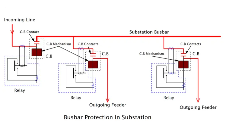
The protection of bus bar installations relies on a coordinated system of specialised equipment. The most widely used and effective method is differential protection. This scheme works by creating a ‘zone of protection’ around the busbar. It uses current transformers (CTs) on all incoming lines and outgoing lines connected to the bus.
A relay, specifically a differential relay, continuously compares the sum of electric currents entering the bus bar zone with the sum of currents leaving it. During normal operation, these sums are equal. However, during a fault within the zone, this balance is disturbed, causing a differential current to flow to the relay.
When the relay detects this imbalance, it sends a trip signal to all the circuit breakers connected to that specific busbar section. These circuit breakers then open, disconnecting all circuits from the faulty bus and effectively isolating the faulty section. This entire process happens in milliseconds, ensuring minimal disruption to the rest of the power system.
This combination of sensitive relays and fast-acting circuit breakers forms a robust protection scheme that keeps the substation and the wider grid safe and reliable. Other components, like a dependable battery bank, ensure the protection system remains powered and ready to act even during a power outage.
Types of Busbar Protection
A single short circuit in a substation can bring an entire power network to a halt. Effective busbar faults detection forms the first line of defence against these catastrophic failures. When a fault strikes, the right protection system acts in milliseconds to isolate the damage and maintain grid stability.
Substation relaying relies on several different methods to keep power flowing safely. Let us explore the primary busbar protection schemes used to safeguard these critical electrical hubs.
Differential Protection of Busbar
Differential protection serves as the most reliable and widely used method for securing the bus bar zone. This system operates on a simple principle based on Kirchhoff’s current law. According to this law, the total current entering a node must equal the total current leaving it.
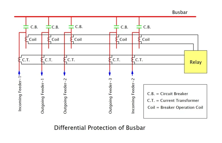
Engineers install current transformers (often called CTs) on all incoming and outgoing circuits connected to the busbar. Under normal conditions, the current entering the bus perfectly balances the current leaving it. The secondary windings of each CT are connected in parallel, forming a closed loop. Because the currents balance out, no circulating current flows through the central relay coil.
However, when an internal fault occurs within the protected zone, this balance instantly collapses. The fault draws massive amounts of current, disrupting the equilibrium. This imbalance generates magnetic flux, which induces a voltage that forces current through the relay coil. The relay immediately sends a trip command to the appropriate circuit breaker. This rapid response safely isolates the busbar before the short circuit causes severe equipment damage.
Crucially, this system remains stable during an external fault. For faults located beyond the defined busbar zone, the busbar itself acts as a conductive pathway, channeling the abnormal current from the source to the external fault location. The CTs still register balanced currents, preventing unnecessary tripping.
Frame Leakage Protection
Frame leakage protection provides a highly effective defence against ground faults. This method involves insulating the switchgear framework from the main ground. Engineers mount the entire busbar assembly on an insulated ground supporting structure.
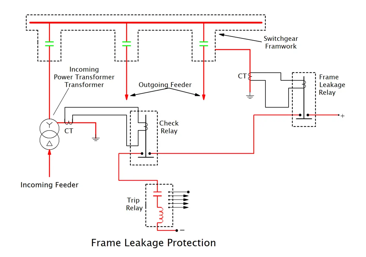
Instead of grounding the equipment directly, they connect the earthed metal framework to ground via a single dedicated path. A current transformer is connected to this specific grounding connection. During normal operation, no current flows through this path.
If a fault causes a live conductor to touch the metal enclosure, the current must travel through this single ground connection to escape. The CT instantly detects this unexpected current flow. The relay then issues a trip command, opening the necessary circuit breaker to clear the fault.
This method only requires one CT, making it a cost-effective choice for many installations. However, it specifically targets ground faults and cannot detect a phase-to-phase fault. Engineers often use it alongside other busbar protection schemes for comprehensive coverage.
Backup Protection for Busbar
Backup protection for busbars is activated when primary protection, such as differential or frame-leakage protection, becomes inoperative or fails to isolate a fault. In a robust protection system, backup devices ensure an added layer of safety for switchgear equipment and the entire grid. Backup protection often uses overcurrent relays or remote tripping from adjacent feeders to isolate the faulty section of the bus bar zone when the primary system doesn’t operate as intended.
This type of protection is crucial in situations where circuit breakers or relays may not act immediately on internal faults. By introducing a time delay, coordination is achieved, so the backup relay operates only if the primary systems fail. In complex substations with multiple bus sections or critical supplying systems, backup protection preserves grid stability by isolating damage and restoring functionality to healthy parts.
Differential Overcurrent Protection for Busbar
Differential overcurrent protection builds on the principles of standard differential schemes but combines them with the operation of an overcurrent relay. This approach uses current transformers (CTs) on all incoming and outgoing lines, as well as special relay circuits designed to respond not just to current imbalances but also to the magnitude of fault current.
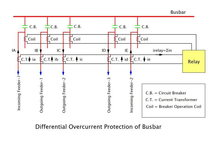
The relay circuit monitors the difference in current entering and leaving the bus section. When an internal fault occurs, not only does an imbalance arise (as in classic differential protection), but the overcurrent relay is also energised if the current exceeds a predetermined value. The combination of current flow analysis, the step-up turns ratio in CTs, and the design of the secondary circuit improves sensitivity, especially for high-magnitude phase-to-phase faults or ground faults.
When the relay detects enough imbalance and overcurrent, it issues a trip command to the circuit breaker. The relay contacts close, energising auxiliary multi-contact arrangements for redundant tripping. This results in swift isolation of the faulty section, ensuring uninterrupted power to healthy feeders and minimising damage to both the conductor bars and switchboard equipment.
Conclusion
The stability of the entire power grid hinges on the effectiveness of its busbar protection. As the central connection point for all incoming and outgoing power, the busbar requires robust, reliable safeguarding. Effective protection schemes are not just a recommendation; they are a fundamental requirement for modern power systems.
Selecting and implementing the right busbar protection strategy is one of the most important decisions in substation engineering. A well-designed system ensures maximum reliability and operational continuity.
Why is busbar protection so important?
Without rapid protective relaying, a busbar fault can cause severe damage to substation equipment, trigger fires, and lead to widespread power outages. Effective protection safeguards physical infrastructure and ensures a continuous supply of electricity.
What are the most common causes of busbar faults?
Most busbar faults are caused by external factors or equipment wear and tear. Common causes include lightning strikes, adverse weather conditions, insulation failure, and animal interference. The accidental dropping of tools during maintenance can also trigger a sudden short circuit.
How fast does a busbar protection system operate?
Speed is absolutely essential to prevent catastrophic damage. Modern protective relay systems operate with incredible speed, typically detecting and isolating a fault in a busbar within just 10 to 20 milliseconds.
What happens if the primary busbar protection fails?
If the primary system fails to operate, backup protection schemes will take over to clear the fault. However, backup systems operate with a slight time delay. This delay can result in more extensive equipment damage and affect a larger portion of the power grid.
Do all substations use the same busbar protection methods?
No. The specific protection scheme depends heavily on the size, voltage level, and layout of the substation. A small distribution substation might use a simple blocking scheme, while a critical high-voltage transmission substation requires advanced numerical differential protection.
I am an electrical engineer and also a blogger. I write informative blog posts on topics related to electrical and electronics engineering. If you are interested in these topics, you are welcome to my site to read these articles.