What is Busbar in Substation and its Types
Imagine an electrical substation as a major traffic interchange for electricity. Power flows in from various sources and must be directed to cities, towns, and neighborhoods. In this complex system, a crucial component serves as the main intersection, ensuring that electrical energy reaches its intended destination safely and efficiently. This component is known as a busbar.
A busbar is essentially a metallic strip or bar, typically made of copper or aluminum, that serves as a central point for collecting and distributing electrical current. Instead of connecting countless wires in a tangled mess, substations use busbars to consolidate incoming power and distribute it to outgoing lines.
This simple yet vital function makes them the backbone of any substation, playing a fundamental role in the reliability and stability of the entire electrical grid that powers our daily lives. This article will help you understand what a busbar is, how it works in an electrical substation, and the various types of busbars used.
What is Busbar System in Substation
An electrical substation is a critical hub in the vast network that delivers electricity to our homes and businesses. Within this complex facility, numerous components work together to manage high-voltage power. Among the most fundamental of these is the busbar system. This system acts as the central nervous system for power distribution inside the substation, ensuring electricity is routed correctly and safely.
What is a Substation Busbar?
A substation busbar is a conductor, or a group of conductors, that serves as a common connection point for multiple electrical circuits. Think of it as a major intersection or junction for electrical current. It collects power from incoming lines and distributes it to outgoing lines. Typically, these busbars are made from highly conductive metals like copper or aluminum, which offer low electric resistance.
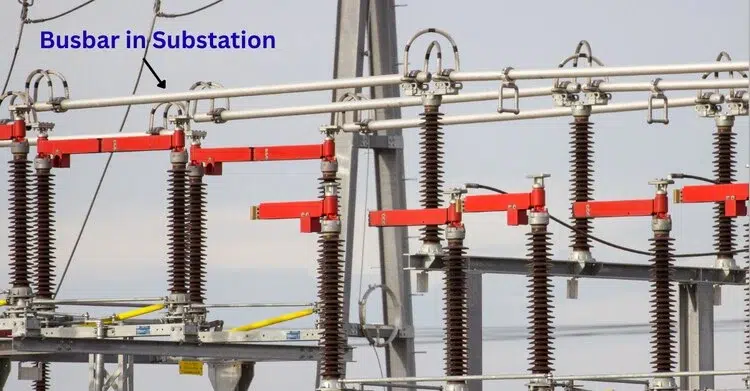
The physical form of a busbar can vary based on the substation’s needs. They come in different shapes, including flat strips, round bars, round tubes, and even a square bar configuration. The specific size of the bus bar is engineered based on the amount of current it needs to carry. In outdoor substations, you might see rigid busbars supported by large steel structures called gantries. An improper electrical connection on a busbar can lead to significant problems, so they are designed for secure and stable performance.
How Do Busbars Work?
The operation of a busbar is straightforward yet vital. In an electrical substation, power arrives through incoming feeders from a power generation source. A direct electrical pathway exists between these feeders and the busbar. The busbar then serves as a single, consolidated energy point. From this central point, multiple outgoing feeders draw the power and direct it towards transformers, distribution lines, and other parts of the grid.
This setup simplifies the substation’s wiring. Instead of connecting every incoming line to every outgoing line—an impossibly complex task—all circuits meet at the busbar. This arrangement provides flexibility to the electrical distribution system. For maintenance or in the event of a fault, a specific circuit can be disconnected from the busbar using an isolator or a circuit breaker, without shutting down the entire system.
What is the Purpose of Busbars?
The primary purpose of a busbar is to provide a reliable and efficient way to distribute electrical energy within a substation. By creating a common junction point, busbars simplify the complex task of routing high-voltage electricity. This organized approach minimizes the risk of faults and makes the system easier to manage.
Another key purpose is economic. Using a busbar system can significantly reduce installation costs and labor costs compared to other wiring methods. The streamlined design also lowers long-term maintenance costs. A well-designed busbar system contributes to efficient and reliable power delivery, which is essential for grid stability. The system is designed to handle immense electrical loads without excessive heat generation, which could otherwise damage equipment.
What is the Main Function of Busbar in Substation?
The main function of electrical bus bar is to provide a low-impedance path for electrical current, ensuring power is distributed with minimal energy loss. As a central electrical component, it ties together various substation components, including transformers, circuit breakers, and feeders.
When a fault occurs on an outgoing line, its corresponding circuit breaker is tripped, disconnecting it from the busbar. This action isolates the fault without affecting the other circuits connected to the same busbar, ensuring the rest of the system continues to operate. The carefully calculated size of the busbars ensures they can handle the total current of all connected circuits without overheating. Ultimately, the busbar serves as the backbone of the electrical substation, ensuring the safe and methodical collection and distribution of power.
Types of Busbar in Substation
In a power system, a substation is a crucial component that controls and distributes electricity from one location to another. At the heart of this process is the busbar. In power distribution, a busbar acts as a common collection point, using conductive bars to unite various incoming and outgoing lines. The reliability, cost, and operational flexibility of a substation depend significantly on its busbar configuration.
Choosing the right electrical bus bar scheme ensures substation continuity and ease of maintenance. An incorrect arrangement can cause the entire substation to shut down during a fault, leading to widespread power outages. Therefore, understanding the different types of busbar arrangements is crucial for electrical engineering students and technicians.
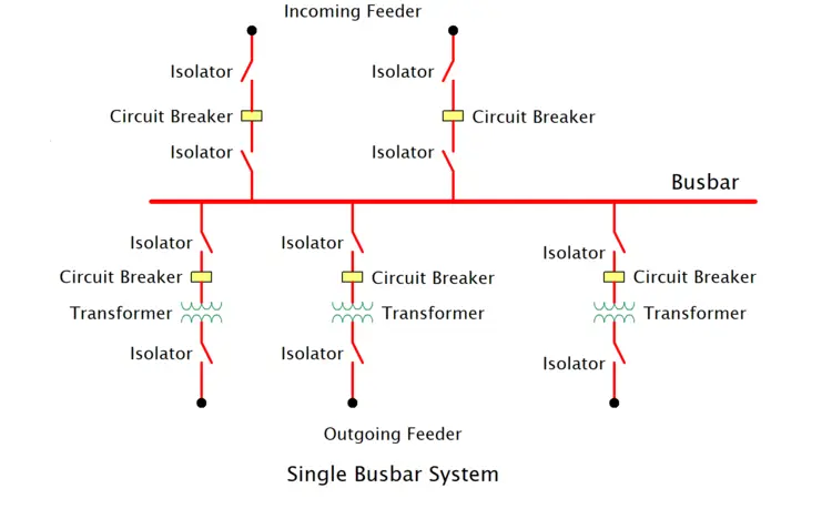
Single Busbar System
This is the simplest and least expensive busbar arrangement. As the name suggests, it has only one main substation busbar to connect all incoming and outgoing lines. A circuit breaker and its corresponding isolators form the connection between each circuit and the main busbar. All feeders, transformers and generators are connected to the same busbar.
Advantages:
- This arrangement is characterised by its fundamental simplicity.
- It has a very low initial cost because it requires less switchgear.
- It is easy to operate and maintain.
Disadvantages:
- Reliability is very low. If a busbar fault occurs, the entire substation shuts down.
- Electrical bus bar maintenance requires a complete shutdown of the entire substation.
Applications: It is typically used for smaller distribution substations and less critical loads, where power continuity is less critical.
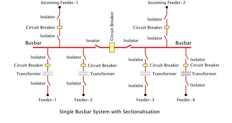
Single Busbar System with Sectionalisation
This is an improved version of the single busbar system. In this system, the busbar is divided into two or more sections using one or more circuit breakers and isolators. In normal operation, the sectionalizer (bus section breaker) is closed, and the busbar operates as a single unit. A single busbar is divided into two sections by a circuit breaker in the middle.
Advantages:
- Reliability is increased. If a fault occurs in one section of the bus bar, only that section is affected, while the other section remains operational.
- Maintenance does not require shutting down the entire substation. While work is being done on one section, supply can be maintained from the other.
Disadvantages:
- It costs slightly more than a simple single busbar system because it requires additional circuit breakers and isolators.
Applications: It is used in large substations where slightly higher reliability is required than a single busbar.
Double Busbar System
This arrangement consists of two identical busbars—a “main busbar” and a “spare/transfer busbar.” Each circuit can be connected to either busbar using bus couplers and isolators.
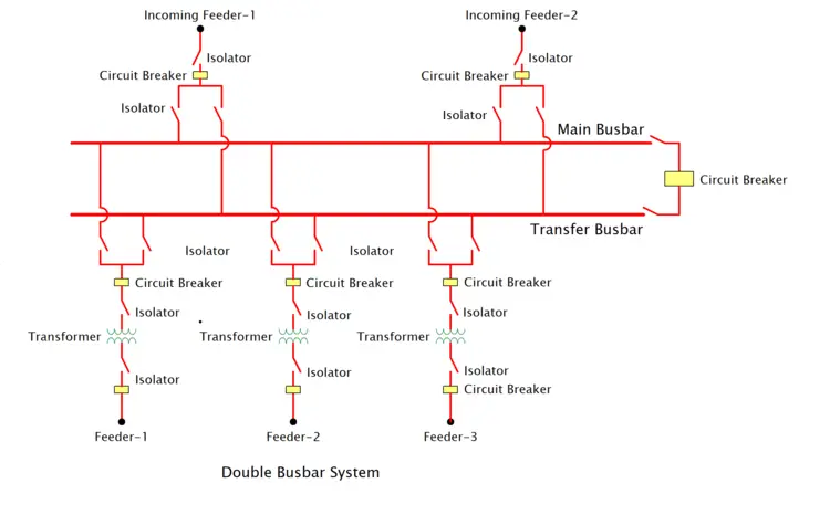
There are two parallel bus bars, allowing each circuit to be connected to either bus. A bus coupler (circuit breaker) connects the two buses.
Advantages:
- Provides great operational flexibility and reliability.
- Maintenance can be performed on any busbar without disrupting any circuits. Loads can be easily transferred between busbars.
- In the event of a fault on one busbar, supply can be restored by transferring all circuits to the other bus.
Disadvantages:
- This costs significantly more because it requires twice as many isolators and an additional bus coupler breaker.
Applications: It is used in large and important substations, such as generating stations and major transmission substations, where a continuous power supply is essential.
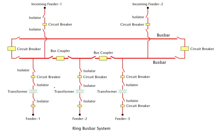
Ring Busbar System
In this arrangement, the electrical bus bars are arranged in a ring, and the circuit breakers form part of the ring. All incoming and outgoing lines are tapped at various points on the ring. The ring contains as many circuit breakers as the number of circuits. The circuit breakers form a closed loop or ring, and each feeder is connected between two breakers.
Advantages:
- Each feeder receives a two-way supply, which increases reliability.
- Even if a circuit breaker is opened for maintenance, all circuits remain operational.
- Cost is lower than a double bus bar system.
Disadvantages:
- It is difficult to add a new circuit to the ring.
- In the event of a fault, the ring opens, and some feeders may become overloaded.
Applications: It is a popular choice for transmission substations where a balance must be struck between reliability and cost.
One and a Half Busbar System
This system is a hybrid of the double-busbar and ring-busbar systems. In this system, two circuits are connected to two busbars through three circuit breakers each. This is why it is called a “one and a half breaker” scheme (3 breakers / 2 circuits = 1.5). There are two busbars, and three circuit breakers are placed between each pair of feeders.
Advantages:
- This provides a very high level of reliability and safety.
- Maintenance of any substation bus bar can be performed without interruption.
- Both circuits can remain operational while maintenance is being performed on any circuit breaker.
Disadvantages:
- Its cost is very high.
- The relaying and control circuits are complex.
Applications: This is the preferred arrangement for EHV (Extra High Voltage) transmission substations and large generating stations, where the highest level of reliability is required.
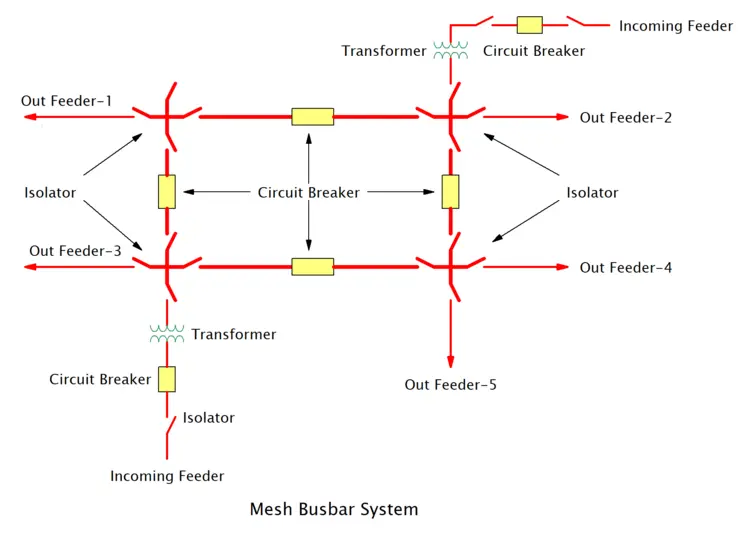
Mesh Busbar System
In a mesh electrical busbar system, all circuits are connected as a single mesh. Each junction in the mesh has a circuit breaker. When the mesh is completely closed, it is called a “full mesh.” All equipment is connected in a grid or mesh pattern. Opening any circuit breaker does not completely isolate any part of the substation.
Advantages:
- This configuration significantly enhances the overall operational dependability.
- Maintenance of any breaker can be performed without interrupting the supply.
- A key advantage of this setup is the minimal requirement for circuit breakers.
Disadvantages:
- Maintenance and operation can be complex.
- Switching operations is difficult.
Applications: It is mainly used in large transmission substations where many circuits have to be connected.
Conclusion:
The choice of busbar arrangement for a substation is a critical engineering decision that depends on many factors, such as cost, maintenance, flexibility, and reliability. A simple single-busbar system may be economical for small applications, while complex systems, such as one-and-a-half-breaker schemes, provide the reliability required for large power stations and the national grid. Each system has its own advantages and disadvantages, and choosing the right scheme is crucial to ensuring an uninterrupted power supply.
FAQ
What is Slack bus in power system
In a power system, a slack bus is used in power flow analysis to balance the system’s active and reactive power by absorbing unknown losses. It serves as a reference point with a fixed voltage magnitude and angle (usually 0°), while its power generation adjusts to ensure system balance.
What is Y Bus in Power System
In a power system, the Y Bus (Admittance Matrix) is a mathematical representation of the network’s admittance (reciprocal of impedance). It is used in power flow analysis to model the relationship between bus voltages and injected currents. Each element in the Y Bus matrix represents the admittance between buses or the self-admittance of a bus.
what is z bus in power system
In a power system, the Z Bus (Impedance Matrix) is the inverse of the Y Bus (Admittance Matrix). It represents the system’s impedance between buses and is used in fault analysis to calculate bus voltages and currents during faults. Each element in the Z Bus matrix indicates the impedance between two buses or the self-impedance of a bus.
What is pq Bus in Power System
In a power system, a PQ Bus (Load Bus) is a type of bus where the active power (P) and reactive power (Q) are specified. The voltage magnitude and angle are calculated during power flow analysis. It represents load points in the system.
I am an electrical engineer and also a blogger. I write informative blog posts on topics related to electrical and electronics engineering. If you are interested in these topics, you are welcome to my site to read these articles.