DC Shunt Motor Working Principle
When you dive into the world of electrical engineering, the direct current motor stands out as a fundamental piece of machinery. Among the different types available, the DC shunt motor holds a special place due to its unique internal design. But what exactly is a DC shunt motor?
At its core, a DC shunt motor is a type of direct current motor with internal windings arranged in a specific layout. Understanding how this motor works helps you grasp the foundational concepts of electromagnetism and machinery. When you know the exact working principle, you can easily identify how energy moves through the system. We will explore exactly how this motor functions, focusing solely on its construction and the principles that drive its motion.
What is the Working Principle of a DC Shunt Motor?
To understand how a DC shunt motor operates, you have to look at how electricity and magnetism interact inside the machine. The fundamental working principle relies entirely on basic electromagnetic laws. When a current-carrying conductor sits inside a magnetic field, it experiences a mechanical force. This exact interaction is what brings the motor to life.
The Role of Parallel Winding and Field Excitation
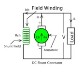
The word “shunt” simply means parallel. In a DC shunt motor, the two main internal components—the armature winding and the field winding—connect in parallel to the main power supply. This parallel winding layout is the defining feature of the motor.
Because both windings are connected directly to the same voltage supply, they receive the same voltage. The field winding consists of many turns of thin wire, which creates a specific resistance. When you turn on the power supply, current splits. A small portion of the current travels into the field winding, initiating a process called field excitation. This excitation generates a steady, constant magnetic field inside the motor. Meanwhile, the remaining current flows into the armature winding, which sits directly within the newly created magnetic field.
How the Motor Converts Electrical Energy Into Mechanical Energy
The primary job of any direct current motor is to convert electrical energy into mechanical energy. In the DC shunt motor, this conversion happens through the interaction between the armature and the field excitation.
Once the power is on, you have a strong magnetic field (from the field winding) and a conductor full of electric current (the armature). According to the laws of electromagnetism, the magnetic field pushes against the current flowing through the armature. This push creates a physical force. Because the armature sits on a rotating shaft, the physical force causes it to spin.
Electricity flows into the parallel winding, magnetic fields interact, and the shaft rotates. Through this continuous electromagnetic interaction, the motor effectively converts incoming electrical energy into mechanical motion.
Converting Electrical Energy to Mechanical Energy: Step-by-Step Process
- Power Supply to the Motor
- When the motor is connected to a DC power source, the electrical energy flows into the motor.
- The power supply is connected in parallel to two main components: the field winding and the armature winding. This parallel connection ensures that both components receive the same voltage.
- Field Winding Generates a Magnetic Field
- The field winding consists of many turns of thin wire with high resistance.
- When current flows through the field winding, it generates a steady magnetic field around the winding. This process is called field excitation.
- This magnetic field remains constant as long as the power supply is active.
- Current Flows Through the Armature Winding
- The armature winding is located on the rotor (the rotating part of the motor).
- When current flows through the armature winding, it interacts with the magnetic field created by the field winding.
- Electromagnetic Force is Generated
- According to Lorentz Force Law, when a current-carrying conductor (the armature winding) is placed in a magnetic field, it experiences a force.
- This force acts perpendicular to both the direction of the current and the magnetic field.
- The interaction between the magnetic field and the current in the armature winding creates a torque (rotational force) on the armature.
- Armature Starts Rotating
- The torque generated causes the armature to rotate.
- The armature is mounted on a shaft, so as it rotates, the shaft also begins to spin.
- This rotational motion is the mechanical energy output of the motor.
- Continuous Energy Conversion
- As the armature rotates, the commutator (a mechanical switch) ensures that the current direction in the armature winding is maintained.
- This keeps the torque in the same direction, allowing the motor to rotate continuously.
- The motor thus continuously converts electrical energy into mechanical energy as long as the power supply is active.
- Output: Mechanical Energy
- The rotating shaft of the motor can now be connected to various mechanical systems (like fans, pumps, or conveyor belts) to perform work.
- The efficiency of this energy conversion depends on the motor’s design and operating conditions.
Types of DC Shunt Motor Principles
When we examine how a direct current motor generates its magnetic field, we find two distinct operational principles. The primary difference lies in how the motor powers its internal coils. By understanding these two methods, you can clearly see how the machine manages its internal energy.

The Self-Excited Principle
In a self-excited DC motor, the machine uses a single, shared electrical supply to power its entire operation. As we established earlier, the internal parts connect in parallel. Because of this parallel setup, the main power supply delivers electricity to both the main rotating part and the stationary magnetic part simultaneously.
When you turn on the main voltage source, the current splits. A specific amount of this electricity travels directly into the field winding. Because the field winding shares the same power source as the rest of the motor, this is called a “self-excited” setup.
The motor relies on a phenomenon called residual magnetism to initiate electromagnetic induction. Even when turned off, the metal inside the motor holds a tiny bit of magnetism. When the single power source pushes electricity through the parallel coils, this small residual magnetism helps build a full, powerful magnetic field. The system sustains itself entirely from that one shared electrical connection.
The Separately Excited Principle
The separately excited principle takes a completely different approach to powering the motor. Instead of sharing a single power supply, this setup uses two completely independent electrical sources.
In this arrangement, the field winding does not connect in parallel with the main motor circuit. Instead, it connects to its own dedicated voltage source. This means you have one power supply supplying power to the field winding to create the magnetic field, and a second, separate power supply driving the main armature circuit.
Because the two circuits remain isolated from each other, the electricity flowing through the magnetic coils has no physical connection to the armature current. The motor still relies on electromagnetic induction to create physical movement, but it does so by combining two entirely separate electrical systems.
Key Differences Between the Two Principles
Understanding the contrast between the self-excited and separately excited principles comes down to analyzing their electrical layouts. Here are the core differences between how these two setups function:
- Power Source Configuration: The self-excited principle uses a single voltage source to power the entire machine. In contrast, the separately excited principle requires two distinct, isolated power supplies to operate.
- Internal Connections: In a self-excited setup, the internal coils are connected in parallel to the main power lines. The separately excited setup completely unlinks these coils, keeping the magnetic and armature circuits physically separated.
- Current Distribution: When dealing with a self-excited principle, the total current from the power supply divides itself between the field and the armature. In the separately excited principle, the armature current and the field current flow from separate sources, so they do not cancel each other out.
- Excitation Dependency: A self-excited motor must have a closed, complete parallel circuit to build its magnetic field. A separately excited motor can generate a full magnetic field even if the main armature circuit is completely disconnected from its power source.

Conclusion
In short, a DC shunt motor has its armature and field windings connected in parallel. This setup converts electrical energy into mechanical energy and maintains stability during operation. There are two main types: one uses the same power supply for both windings (self-excited), and the other uses separate power sources (separately excited). Understanding the basics is not only helpful for learning how the motor works, but it is also essential for anyone involved in electrical engineering or industrial technology.
Mastering the working principles and types of DC shunt motors makes it easier to select, use, and repair them in real-world situations. DC shunt motors play a key role in factories, automation, and machinery that require steady speed, and their reliable operation has made them the backbone of modern electrical systems. This knowledge serves as the foundation for deeper studies and practical troubleshooting of electrical machinery.
FAQ
-
What is DC Shunt Motor
A parallel dc motor is an electric motor in which the armature and field windings are connected in parallel. It is ideal for stable speed, high efficiency, and reliability, and is used in many industrial applications such as lathes, pumps, and conveyor belts.
-
Can DC Shunt Motor Start at No Load
Yes, a parallel dc motor can be started without a load because its field winding and armature winding are connected in parallel, which creates a sufficient magnetic field.
-
Can DC Shunt Motor Work on AC
No, a parallel dc motor cannot run on AC because:
(a) On AC power, the direction of current in both the field and armature is constantly changing, causing the motor to operate poorly.
(a) Excessive eddy currents generated at an AC power source can cause the motor to overheat.
(a) On AC power, excessive sparking may occur in the commutator and brushes, potentially causing damage to the device. -
How DC Shunt Motor Change Direction
To change the direction of a DC shunt wound motor, the direction of current in either the armature winding or the field winding is altered.
-
What is Back EMF in DC Shunt Motor
Back EMF in a shunt wound dc motor is a voltage produced when the armature rotates, acting opposite to the supply voltage.
I am an electrical engineer and also a blogger. I write informative blog posts on topics related to electrical and electronics engineering. If you are interested in these topics, you are welcome to my site to read these articles.